Series RLC-Circuit
Category : JEE Main & Advanced
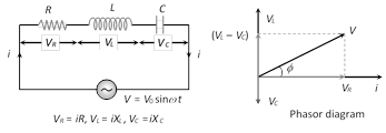
(1) Equation of current : \[i={{i}_{0}}\sin (\omega \,t\pm \varphi )\]; where \[{{i}_{0}}=\frac{{{V}_{0}}}{Z}\]
(2) Equation of voltage : From phasor diagram \[V=\sqrt{V_{R}^{2}+{{({{V}_{L}}-{{V}_{C}})}^{2}}}\]
(3) Impedance of the circuit : \[Z=\sqrt{{{R}^{2}}+{{({{X}_{L}}-{{X}_{C}})}^{2}}}=\sqrt{{{R}^{2}}+{{\left( \omega \,L-\frac{1}{\omega C} \right)}^{2}}}\]
(4) Phase difference : From phasor diagram \[\tan \varphi =\frac{{{V}_{L}}-{{V}_{C}}}{{{V}_{R}}}=\frac{{{X}_{L}}-{{X}_{C}}}{R}=\frac{\omega \,L-\frac{1}{\omega \,C}}{R}=\frac{2\pi \nu \,L-\frac{1}{2\pi \nu \,C}}{R}\]
(5) If net reactance is inductive : Circuit behaves as LR circuit
(6) If net reactance is capacitive : Circuit behave as CR circuit
(7) If net reactance is zero : Means \[X={{X}_{L}}-{{X}_{C}}=0\]
\[\Rightarrow \] \[{{X}_{L}}={{X}_{C}}\] . This is the condition of resonance
(8) At resonance (series resonant circuit)
(i) \[{{X}_{L}}={{X}_{C}}\Rightarrow {{Z}_{\min }}=R\] i.e. circuit behaves as resistive circuit
(ii) \[{{V}_{L}}={{V}_{C}}\Rightarrow V={{V}_{R}}\] i.e. whole applied voltage appeared across the resistance
(iii) Phase difference : \[\phi ={{0}^{o}}\]\[\Rightarrow \]\[p.f.\,=\cos \phi =1\]
(iv) Power consumption \[P={{V}_{rms}}\,{{i}_{rms}}=\frac{1}{2}{{V}_{0}}{{i}_{0}}\]
(v) Current in the circuit is maximum and it is \[{{i}_{0}}=\frac{{{V}_{0}}}{R}\]
(vi) These circuit are used for voltage amplification and as selector circuits in wireless telegraphy.
(9) Resonant frequency (Natural frequency)
At resonance \[{{X}_{L}}={{X}_{C}}\]\[\Rightarrow \] \[{{\omega }_{0}}L=\frac{1}{{{\omega }_{0}}C}\]\[\Rightarrow \]\[{{\omega }_{0}}=\frac{1}{\sqrt{LC}}\frac{rad}{sec}\]\[\Rightarrow \]\[{{\nu }_{0}}=\frac{1}{2\pi \sqrt{LC}}Hz\,(\text{or}\,cps)\]
(Resonant frequency doesn't depend upon the resistance of the circuit)
(10) Half power frequencies and band width : The frequencies at which the power in the circuit is half of the maximum power (The power at resonance), are called half power frequencies.
(i) The current in the circuit at half power frequencies (HPF) is \[\frac{1}{\sqrt{2}}\] or 0.707 or 70.7% of maximum current (current at resonance).
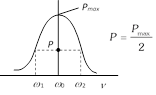
(ii) There are two half power frequencies
(a) \[{{\omega }_{1}}\to \] called lower half power frequency. At this frequency the circuit is capacitive.
(b) \[{{\omega }_{2}}\to \] called upper half power frequency. It is greater than \[{{\omega }_{0}}\]. At this frequency the circuit is inductive.
(iii) Band width \[(\Delta \omega )\]: The difference of half power frequencies \[{{\omega }_{1}}\] and \[{{\omega }_{2}}\] is called band width \[(\Delta \omega )\]and \[\Delta \omega ={{\omega }_{2}}-{{\omega }_{1}}\]. For series resonant circuit it can be proved \[\Delta \omega =\left( \frac{R}{L} \right)\]
(11) Quality factor (Q-factor) of series resonant circuit
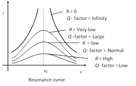
(i) The characteristic of a series resonant circuit is determined by the quality factor (Q - factor) of the circuit.
(ii) It defines sharpness of \[i-v\] curve at resonance when Q - factor is large, the sharpness of resonance curve is more and vice-versa.
(iii) Q - factor also defined as follows
Q - factor \[=2\pi \times \frac{\text{Max}\text{. energy stored}}{\text{Energy dissipation }}\]
\[=\frac{2\pi }{T}\times \frac{\text{Max}\text{. energy stored}}{\text{Mean power dissipated}}\]\[=\frac{\text{Resonant frequency}}{\text{Band width}}=\frac{{{\omega }_{0}}}{\Delta \omega }\]
(iv) Q - factor \[=\frac{{{V}_{L}}}{{{V}_{R}}}\] or \[\frac{{{V}_{C}}}{{{V}_{R}}}\]\[=\frac{{{\omega }_{0}}L}{R}\,\,\text{or}\,\,\frac{1}{{{\omega }_{0}}CR}\]
\[\Rightarrow Q\text{-factor}=\frac{1}{R}\sqrt{\frac{L}{C}}\]


You need to login to perform this action.
You will be redirected in
3 sec

