A) \[{{X}_{1}}\] is an inductor and \[{{X}_{2}}\] is a capacitor
B) \[{{X}_{1}}\] is a resistor and \[{{X}_{2}}\] is a capacitor
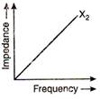
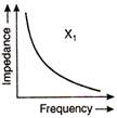
C) \[{{X}_{1}}\] is a capacitor and \[{{X}_{2}}\] is an inductor
D) \[{{X}_{1}}\] is an inductor and \[{{X}_{2}}\] is a resistor
Correct Answer: C
Solution :
The inductive reactance in A.C. circuit \[{{X}_{L}}={{X}_{2}}=\omega L\] \[\Rightarrow \]\[{{X}_{2}}\propto \omega \] \[{{X}_{2}}\propto f\] \[(\therefore \omega =2\pi f)\] The capacitive reactance \[{{X}_{C}}={{X}_{1}}=\frac{1}{\omega C}\] \[\Rightarrow \] \[{{X}_{1}}\propto \frac{1}{\omega }\] \[{{X}_{1}}\propto \frac{1}{f}\] \[(\therefore \omega =2\pi f)\] Hence, it is obvious that \[{{X}_{1}}\] is a capacitor and \[{{X}_{2}}\] is an inductor.


You need to login to perform this action.
You will be redirected in
3 sec

