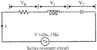
 Resonance Properties of Series RLC Circuit
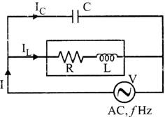 Properties of Parallel Resonant LRC Circuit
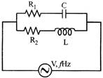 Let \[{{Y}_{1}}\]= admittance of \[{{R}_{1}}C\]circuit
\[{{Y}_{2}}\]= admittance of\[{{R}_{2}}L\] circuit
Y= net admittance \[={{Y}_{1}}+{{Y}_{2}}\]
\[=\left[ \frac{{{R}_{1}}}{R_{1}^{2}+X_{C}^{2}}+\frac{{{R}_{2}}}{R_{2}^{2}+X_{L}^{2}} \right]+j\,\,\left[ \frac{{{X}_{C}}}{R_{1}^{2}+X_{C}^{2}}-\frac{{{X}_{L}}}{R_{2}^{2}+X_{L}^{2}} \right]\]
Important Point
Let \[{{Y}_{1}}\]= admittance of \[{{R}_{1}}C\]circuit
\[{{Y}_{2}}\]= admittance of\[{{R}_{2}}L\] circuit
Y= net admittance \[={{Y}_{1}}+{{Y}_{2}}\]
\[=\left[ \frac{{{R}_{1}}}{R_{1}^{2}+X_{C}^{2}}+\frac{{{R}_{2}}}{R_{2}^{2}+X_{L}^{2}} \right]+j\,\,\left[ \frac{{{X}_{C}}}{R_{1}^{2}+X_{C}^{2}}-\frac{{{X}_{L}}}{R_{2}^{2}+X_{L}^{2}} \right]\]
Important Point
 Phaser diagram
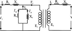
From the equivalent circuit of transformer, it can concluded that
\[{{E}_{2}}={{V}_{2}}+{{I}_{2}}{{R}_{2}}+{{I}_{2}}{{X}_{2}}\]
\[{{I}_{1}}={{I}_{0}}+{{I}_{2}}'\]
\[{{I}_{0}}={{I}_{W}}+{{I}_{\mu }}\]
\[{{V}_{1}}={{E}_{1}}+{{I}_{1}}{{R}_{1}}+{{I}_{1}}{{X}_{1}}\]
Phaser diagram is showing in fig.
Phaser diagram
From the equivalent circuit of transformer, it can concluded that
\[{{E}_{2}}={{V}_{2}}+{{I}_{2}}{{R}_{2}}+{{I}_{2}}{{X}_{2}}\]
\[{{I}_{1}}={{I}_{0}}+{{I}_{2}}'\]
\[{{I}_{0}}={{I}_{W}}+{{I}_{\mu }}\]
\[{{V}_{1}}={{E}_{1}}+{{I}_{1}}{{R}_{1}}+{{I}_{1}}{{X}_{1}}\]
Phaser diagram is showing in fig.
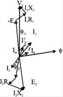 Fig. Phaser diagram
THREE PHASE TRANSFORMER
A three phase transformer or\[3-\phi \]transformer can be constructed either by connecting together three single-phase transformers, thereby forming a so-called three phase transformer bank or b) using one pre-assembled and balanced three phase transformers which consists of three pairs of single phase windings mounted onto one single laminated core.
In the case of three phase transformer windings, three forms of connection are possible: "star" (wye), "delta" (mesh) and "interconnected-star" (zig-zag). The combinations of the three windings may be with the primary delta-connected and the secondary star-connected, or star-delta, star-star or delta-delta, depending on the transformers use as shown in fig. When transformers are used to provide three or more phases they are generally referred to as a Polyphase Transformer.
Fig. Phaser diagram
THREE PHASE TRANSFORMER
A three phase transformer or\[3-\phi \]transformer can be constructed either by connecting together three single-phase transformers, thereby forming a so-called three phase transformer bank or b) using one pre-assembled and balanced three phase transformers which consists of three pairs of single phase windings mounted onto one single laminated core.
In the case of three phase transformer windings, three forms of connection are possible: "star" (wye), "delta" (mesh) and "interconnected-star" (zig-zag). The combinations of the three windings may be with the primary delta-connected and the secondary star-connected, or star-delta, star-star or delta-delta, depending on the transformers use as shown in fig. When transformers are used to provide three or more phases they are generally referred to as a Polyphase Transformer.
|
Primary configuration |
Secondary configuration |
|
Delta (mesh) |
more...
Power System
BASIC POWER GENERATIONS CONCEPT
Energy exists in various forms like mechanical energy, electrical energy, thermal energy and so on. One form of energy can be converted into another form by suitable arrangements. Out of these forms, electrical energy is preferred due to the following reasons.
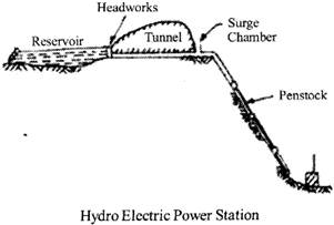
 (B) Hydro-electric Power Stations
These convert energy of falling water (hydraulic) into Electrical energy The entire arrangements can be divided into the following stages for the sake of simplicity:
(B) Hydro-electric Power Stations
These convert energy of falling water (hydraulic) into Electrical energy The entire arrangements can be divided into the following stages for the sake of simplicity:
 (C) Nuclear Power Stations
These convert nuclear energy into electrical energy.
Nuclear power reactor:
Nuclear power reactor is basically that part of nuclear power plant where energy released as a result of nuclear fission of radioactive material is utilized to heat the coolant which may in turn generate steam or be used in a gas turbine. The nuclear reactor may thus be regarded as a substitute for the boiler fire box of steam plant or combustion chamber or a gas turbine plane. The steam or the gas may be used as working fluid in nuclear power plant. The nuclear power plant maybe of steam driven turbine or gas driven turbine as per the choice of the fluid.
(C) Nuclear Power Stations
These convert nuclear energy into electrical energy.
Nuclear power reactor:
Nuclear power reactor is basically that part of nuclear power plant where energy released as a result of nuclear fission of radioactive material is utilized to heat the coolant which may in turn generate steam or be used in a gas turbine. The nuclear reactor may thus be regarded as a substitute for the boiler fire box of steam plant or combustion chamber or a gas turbine plane. The steam or the gas may be used as working fluid in nuclear power plant. The nuclear power plant maybe of steam driven turbine or gas driven turbine as per the choice of the fluid.
 The following Junctions are associated with the working of nuclear reactor:
(i) Producing a chain reacting or critical system,
(ii) Controlling the level of power release from the system,
(iii) Using spare neutrons to convert fertile into fissile material,
(iv)Protecting personnel from harmful radiations emanating from the core.
TRANSMISSION
At the more...
The following Junctions are associated with the working of nuclear reactor:
(i) Producing a chain reacting or critical system,
(ii) Controlling the level of power release from the system,
(iii) Using spare neutrons to convert fertile into fissile material,
(iv)Protecting personnel from harmful radiations emanating from the core.
TRANSMISSION
At the more...
Control System
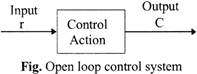
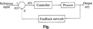
CONTROL SYSTEM
It is an arrangement of different physical components in such a way that we get the desired output from the input.
Classification of Control System
 For example: traffic light, tap of water etc.
Advantages: These systems are simple in construction & design; economic in nature; easy from the maintenance point of view, have high stability & are convenient to use when the output is difficult to measure.
Disadvantages: These systems are not accurate & reliable as the accuracy depends on the calibration of the inputs & their operation is affected due to the presence of non-linearities in the elements.
For example: traffic light, tap of water etc.
Advantages: These systems are simple in construction & design; economic in nature; easy from the maintenance point of view, have high stability & are convenient to use when the output is difficult to measure.
Disadvantages: These systems are not accurate & reliable as the accuracy depends on the calibration of the inputs & their operation is affected due to the presence of non-linearities in the elements.
 There are two types of feedback:
1) Positive feedback
2) Negative feedback
Positive feedback: When the output which is fed as an input to the system, is in the same phase with the input, then this feedback increases the input or it is added to the input. The positive feedback is used in oscillator circuits.
For positive feedback, error signal \[=r(t)+c(t)\]
There are two types of feedback:
1) Positive feedback
2) Negative feedback
Positive feedback: When the output which is fed as an input to the system, is in the same phase with the input, then this feedback increases the input or it is added to the input. The positive feedback is used in oscillator circuits.
For positive feedback, error signal \[=r(t)+c(t)\]
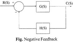
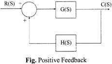 Negative feedback: When the output which is fed as an input to the system, is in a completely opposite phase to the input, then this feedback reduces the input or is subtracted from the input. This feedback helps in stabilizing the gain of the amplifier. Negative feedback is used in amplifier circuits.
For negative feedback, error signal =r (t) - c (t)
Negative feedback: When the output which is fed as an input to the system, is in a completely opposite phase to the input, then this feedback reduces the input or is subtracted from the input. This feedback helps in stabilizing the gain of the amplifier. Negative feedback is used in amplifier circuits.
For negative feedback, error signal =r (t) - c (t)
 Effects of Feedback:
Electrical Measurement and Instrumentation
The measurement methods can be analog or digital methods, deflection or null methods, active or passive methods, direct or indirect methods and absolute or secondary methods. Measurement generally involves an instruments as a physical means of determining an unknown quantity or a variable called the parameter.
The instrument is a means for determining the value or magnitude of the measured. The instruments can also be divided into separate classes according to several criteria as, analog or digital instrument, deflection or null type instruments, power operated (active) or self generating (passive) instruments, contacting or non contacting instruments, mechanical or electrical instruments and or control instruments.
CLASSIFICATION OF INSTRUMENTS
Permanent Magnet Moving Coil Instrument
Utlization of Electrical Energy
In electrical engineering, utilization factor, is the ratio of the maximum load which could be drawn to the rated capacity of the system, this is closely related to the concept of Load factor The Load factor is the ratio of the load that a piece of equipment actually draws (time averaged) when it is in operation to the load it could draw (which we call full load).
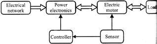
ELECTRICAL DRIVE
Electrical drive system is widely used in large number of industrial and domestic applications like factories, transportation systems, textile mills, fans, pumps, motors, robots etc.
The main advantage of this concept is, the motion control is easily optimized with the help of drive. In very simple words, the systems which control the motion of the electrical machines, are known as electrical drives.
A typical drive system is assembled with a electric motor and a sophisticated control system that controls the rotation of the motor shaft.
Now days, this control can be done easily with the help of software. So, the controlling becomes more and more accurate and this concept of drive also provides the ease of use.
Drives are employed as prime movers for diesel or petrol engines, gas or steam turbines, hydraulic motors and electric motors.
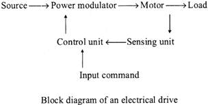
The very basic block diagram an electric drives is shown below.
The load in the figure represents various types of equipment’s which consist of electric motor, like fans, pumps, washing machines etc
 CLASSIFICATION OF ELECTRIC DRIVES
The classification of electrical drives can be done depending upon the various components of the drive system. Now according to the design, the drives can be classified into three types such as single-motor drive group motor drive and multi motor drive.
The single motor types are the very basic type of drive which are mainly used in simple metal working, house hold appliances etc Group electric drives are used in modem industries because of various complexities. Multi motor drives are used in heavy industries or where multiple motoring units are required such as railway transport. If we divide from another point of view, these drives are of two types:
CLASSIFICATION OF ELECTRIC DRIVES
The classification of electrical drives can be done depending upon the various components of the drive system. Now according to the design, the drives can be classified into three types such as single-motor drive group motor drive and multi motor drive.
The single motor types are the very basic type of drive which are mainly used in simple metal working, house hold appliances etc Group electric drives are used in modem industries because of various complexities. Multi motor drives are used in heavy industries or where multiple motoring units are required such as railway transport. If we divide from another point of view, these drives are of two types:
 ELECTRICAL MOTOR
The electrical motor is a device that has brought about one the more...
ELECTRICAL MOTOR
The electrical motor is a device that has brought about one the more...
Basic Electronics
Electronics is considered to be a branch of Physics and Electrical engineering, Electronics is the science of controlling electrical energy electrically, in which the electrons have a fundamental role. Electronics deals with electrical circuits that involve active
Electrical components such as vacuum tubes, transistors, diodes, migrated circuits, associated passive electrical components, and interconnection technologies. Commonly, electronic devices contain circuitry consisting primarily or exclusively of active semiconductors supplemented with passive elements; such a circuit is described as an electronic circuit.
Industrial Electronics
Insustrial electronics is a branch of electronics that deals with power electronic devices such as thyristors, SCRs, AC/DC drives, meters, sensors, analyzers, load cells automatic test equipment, multi-meters, data recorders, relays, resistors, semiconductors, transistors, waveguides, scopes, amplifiers, radio frequency (RF) circuit boards, timers, counters, etc. It covers all of the methods
And facets of: control systems, instrumentation, mechanism and diagnosis, signal processing and automation of various industrial applications. The core research areas of industrial electronics include electrical power machine designs, power conditioning and power semiconductor devices, A lot of consideration is given to power economy and energy management in consumer electronic products.
The scope of industrial electronics ranges from the design and maintenance of simple electrical fuses to complicated programmable logic controllers (PLCs), solid-state devices and drives. Industrial electronics can handle the automation of all types of modem day electrical and mechanical industrial processes, Some of the specialty equipment used in industrial electronics includes: variable frequency converter and inverter drives, human machine interfaces, hydraulic, positioners and computer or microprocessor controlled robotics.
Electronic Components and Their Functions
Communication System
MODULATION
The process of impressing low-frequency information to be transmitted on to a high-frequency wave, called the carrier wave, by changing the characteristics of either its amplitude, frequency, or phase angle is called modulation. The main function of the carrier wave is to carry the audio or video signal from the transmitter to the receiver. The wave that is resulted due to superimposition of audio signal and carrier wave is called the modulated wave.
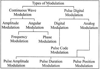
Types of Modulation
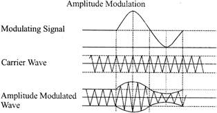
 AMPLITUDE MODULATION (AM)
The method of varying amplitude of a high frequency carrier wave in accordance with the information to be transmitted, keeping the frequency and phase of the carrier wave unchanged is called Amplitude Modulation. The information is considered as the modulating signal and it is superimposed on the carrier wave by applying both of them to the modulator. The detailed diagram showing the amplitude modulation process is given below.
AMPLITUDE MODULATION (AM)
The method of varying amplitude of a high frequency carrier wave in accordance with the information to be transmitted, keeping the frequency and phase of the carrier wave unchanged is called Amplitude Modulation. The information is considered as the modulating signal and it is superimposed on the carrier wave by applying both of them to the modulator. The detailed diagram showing the amplitude modulation process is given below.
 Modulation Index (m)
The ratio between the amplitude change of carrier wave to the amplitude of the normal carrier wave is called modulation index-
It is represented by the letter 'm'.
It can also be defined as the range in which the amplitude of the carrier wave is varied by the modulating signal.
\[m={{V}_{m}}/{{V}_{c}}\]
Percentage modulation, \[%\,\,m={{m}^{*}}100={{V}_{m}}/{{V}_{c}}*100\]
The percentage modulation lies between 0 and 80%.
Power Relations in an AM wave
A modulated wave has more power than had by the carrier wave before modulating. The total power components in amplitude modulation can be written as:
\[{{P}_{total}}={{P}_{carrier}}+{{P}_{LSB}}+{{P}_{USB}}\]
Considering additional resistance like antenna resistance R.
\[{{P}_{carrier}}={{[({{V}_{c}}/\sqrt{2})/R]}^{2}}={{V}^{2}}_{C}/2R\]
ANGLE MODULATION
In the angle modulation, again there are two different types of modulations.
Frequency modulation.
Phase modulation.
Modulation Index (m)
The ratio between the amplitude change of carrier wave to the amplitude of the normal carrier wave is called modulation index-
It is represented by the letter 'm'.
It can also be defined as the range in which the amplitude of the carrier wave is varied by the modulating signal.
\[m={{V}_{m}}/{{V}_{c}}\]
Percentage modulation, \[%\,\,m={{m}^{*}}100={{V}_{m}}/{{V}_{c}}*100\]
The percentage modulation lies between 0 and 80%.
Power Relations in an AM wave
A modulated wave has more power than had by the carrier wave before modulating. The total power components in amplitude modulation can be written as:
\[{{P}_{total}}={{P}_{carrier}}+{{P}_{LSB}}+{{P}_{USB}}\]
Considering additional resistance like antenna resistance R.
\[{{P}_{carrier}}={{[({{V}_{c}}/\sqrt{2})/R]}^{2}}={{V}^{2}}_{C}/2R\]
ANGLE MODULATION
In the angle modulation, again there are two different types of modulations.
Frequency modulation.
Phase modulation.
Radio Communication and Radar Systems
ROBOTIC RADIO COMMUNICATIONS SYSTEMS
The System "Wireless Technology or Radio Based Robot
Communication System" is developed for the purpose of achieving tasks that are almost impossible for the humans and for using them in hazard prone areas. The system consists of a master robot slave robot, voice module and the communication takes place with the help of a voice module. The signal is transmitted and received by the zigbee networks installed on every wireless module. The commands are given only to the master robot using the voice module and this is transmitted to the master robot via zigbee. The master robot performs the actions commanded to it, transfers the same commands to the slave robot(s) and hence performs the same actions as the master robot does. Here the zigbee in voice module acts as a transmitter, in master robot both a transmitter as well as a receiver and only as a receiver in the slave robot.
Zigbee Technology Zigbee is the name of a specification that suites high level communication protocols using small, low-power digital radios based on the IEEE 802.15.4 standard for wireless personal area networks (WPANs), such as wireless headphones connecting cell phones via short-range radio. The technology is intended to be simpler and cheaper than other WPANs, such as Bluetooth. Zigbee is targeted at radio frequency (RF) applications which require a low data rate, long battery life, and secure networking.
 .
Zigbee Module
Zigbee is a wireless technology developed as an open global standard to address the unique needs of low-cost, low-power wireless M2M networks. The Zigbee standard operates on the IEEE 802.15.4 physical radio specification and operates in unlicensed bands including 2.4 GHz, 900 MHz and 868 MHz Zigbee builds upon the physical layer and medium access control defined
In IEEE standard 802, 15.4 (2003 version) for low-rate WPAN's.
The specification goes on to complete the standard by adding four main components: network layer, application layer, Zigbee device objects (ZDO's) and manufacturer-defined application objects which allow for customization and favor total integration.
Radio waves
Radio waves are a type of electromagnetic radiation with wavelengths in the electromagnetic spectrum longer than infrared-light. Radio waves have frequencies as high as 300 GHz to as low as 3 kHz, though some definitions describe waves above 1 or 3 GHz as microwaves, or include waves of any lower frequency. At 300 GHz, the corresponding wavelength is 1 mm (0.039 in), and at 3 kHz is 100 km (62 mi). Like all other electromagnetic waves, they travel at the speed of light. Naturally occurring radio waves are generated by lightning, or by astronomical objects.
The basic building block of radio communications is a radio wave. Like waves on a pond, a radio wave is a series of repeating peaks and valleys. The entire pattern of a wave, before it repeats itself, is called a cycle. The wavelength is the distance a more... .
Zigbee Module
Zigbee is a wireless technology developed as an open global standard to address the unique needs of low-cost, low-power wireless M2M networks. The Zigbee standard operates on the IEEE 802.15.4 physical radio specification and operates in unlicensed bands including 2.4 GHz, 900 MHz and 868 MHz Zigbee builds upon the physical layer and medium access control defined
In IEEE standard 802, 15.4 (2003 version) for low-rate WPAN's.
The specification goes on to complete the standard by adding four main components: network layer, application layer, Zigbee device objects (ZDO's) and manufacturer-defined application objects which allow for customization and favor total integration.
Radio waves
Radio waves are a type of electromagnetic radiation with wavelengths in the electromagnetic spectrum longer than infrared-light. Radio waves have frequencies as high as 300 GHz to as low as 3 kHz, though some definitions describe waves above 1 or 3 GHz as microwaves, or include waves of any lower frequency. At 300 GHz, the corresponding wavelength is 1 mm (0.039 in), and at 3 kHz is 100 km (62 mi). Like all other electromagnetic waves, they travel at the speed of light. Naturally occurring radio waves are generated by lightning, or by astronomical objects.
The basic building block of radio communications is a radio wave. Like waves on a pond, a radio wave is a series of repeating peaks and valleys. The entire pattern of a wave, before it repeats itself, is called a cycle. The wavelength is the distance a more... Current Affairs CategoriesArchive
Trending Current Affairs


You need to login to perform this action. |

