Switching Circuits
Category : JEE Main & Advanced
One of the major practical application of Boolean algebra is to the switching systems (an electrical network consisting of switches) that involves two state devices. The simplest possible example of such a device is an ordinary ON-OFF switch.
By a switch we mean a contact or a device in an electric circuit which lets (or does not let) the current to flow through the circuit. The switch can assume two states ‘closed’ or ‘open’ (ON or OFF). In the first case the current flows and in the second the current does not flow.
Symbols \[a,\,b,\,c,\,p,\,q,\,r,\,x,y,\,z\],..... etc. will denote switches in a circuit.
There are two basic ways in which switches are generally interconnected.
(i) Series
(ii) Parallel
(i) Series : Two switches a, b are said to be connected ‘in series’ if the current can pass only when both are in closed state and the current does not flow if any one or both are open. The following diagram will show this circuit.

![]()
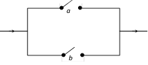
(ii) Parallel : Two switches \[a,b\] are said to be connected ?in parallel? if current flows when any one or both are closed, and current does not pass when both are open. The following diagram will represent this circuit given by \[a\vee b\].
If two switches in a circuit be such that both are open (closed) simultaneously, we shall represent them by the same letter. Again if two switches be such that one is open iff the other is closed, we represent them by a and a¢. The value of a close switch or when it is on is equal to 1 and when it is open or off is equal to 0. An open switch r is indicated in the diagram as follows :
![]()
A closed switch r is indicated in the diagram as follows :
![]()
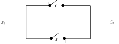
(i) Boolean Multiplication : The two switches r and s in the series will perform the operation of Boolean multiplication.
![]()
Clearly, the current will not pass from point \[{{S}_{1}}\] to \[{{S}_{2}}\] when either or both r, s are open. It will pass only when both are closed.
| r | s | \[r\wedge s\] |
| 1 | 1 | 1 |
| 1 | 0 | 0 |
| 0 | 1 | 0 |
| 0 | 0 | 0 |
The operation is true only in one of the four cases i.e. when both the switches are closed. (ii) Boolean Addition : In the case of an operation of addition the two switches will be in the parallel series as shown below.
The circuit shows that the current will pass when either or both the switches are closed. It will not pass only when both are open.
| r | s | \[r\vee s\] |
| 1 | 1 | 1 |
| 1 | 0 | 1 |
| 0 | 1 | 1 |
| 0 | 0 | 0 |
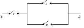
The operation is not true only in one of the four cases i.e., when both r and s are open. (iii) Circuits with composite operations : (a) Circuit showing : \[r\wedge (s\vee q)\]
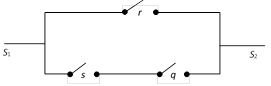
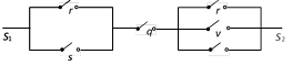
(ii) Circuit showing \[r\vee (s\wedge q)\]
(iii) Circuit showing \[(r\vee s)\wedge (r\vee q)\]
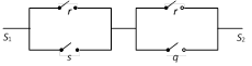
(iv) Circuit for : \[(r\vee s)\,q\,(u\vee v\vee w)\]
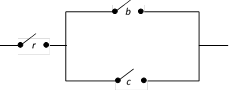
Simplification of circuits : Simplification of a circuit would normally mean the least complicated circuit with minimum cost and best results. This would be governed by various factors like the cost of equipment, positioning and number of switches, types of material used etc. For us, simplification of circuits would mean lesser number of switches which we achieve by using different properties of Boolean algebra. e.g., Consider the circuits given by \[(a\wedge b)\vee (a\wedge c)\] This is represented by
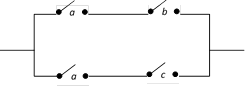
Since \[(a\wedge b)\vee (a\wedge c)=a\wedge (b\vee c)\] \[\therefore \] The circuit could be simplified to


You need to login to perform this action.
You will be redirected in
3 sec

