Impedance of Line
Category : JEE Main & Advanced
Each portion of the transmission line can be considered as a small inductor, resistor and capacitor as shown.
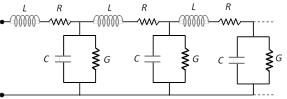
(1) Such inductors, resistors and capacitors are distributed throughout the transmission line. As a result each length of transmission line has a characteristic impedance.
(2) In case of co-axial cable, the dielectric can be represented by a shunt resistance G.
(3) When co-axial cable is used to transmit a radio frequency signal, \[{{X}_{L}}\] and \[{{X}_{C}}\] are large as compared to R and G respectively. Hence R and G can be neglected.
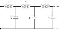
(4) In co-axial cable, R is zero, so no loss of energy and hence no attenuation of frequency signal occurs when transmitted along it. That's why co-axial cables are specially used in cable TV network.
(5) Characteristic impedance \[({{Z}_{0}})\] : It is defined as the impedance measured at the input of a line of infinite length.
For parallel line \[{{Z}_{0}}=\frac{276}{\sqrt{k}}\log \frac{2s}{d}\]
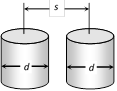
d = Diameter of each wire
s = Separation between the two wires
k = Dielectric constant of the insulating medium
For co-axial line wire \[{{Z}_{0}}=\frac{138}{\sqrt{k}}\log \frac{D}{d}\]
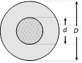
d = Diameter of inner conductor
D = Diameter of outer conductor
At radio frequency \[{{Z}_{0}}=\sqrt{\frac{L}{C}}\]
the usual range of characteristic impedance for parallel wire lines is \[150\,\Omega \] to \[600\,\Omega \] and for co-axial wire it is \[40\,\Omega \] to \[150\,\Omega \].
(6) Velocity factor of a line (v. f.) : It is the ratio of reduction of speed of light in the dielectric of the cable
\[v.f.=\frac{v}{c}=\frac{\text{Speed of light in medium}}{\text{Speed of light in vacuum}}=\frac{1}{\sqrt{K}}\]
For a line v.f. is generally of the order of 0.6 to 0.9.


You need to login to perform this action.
You will be redirected in
3 sec

