Transistor as an Oscillator
Category : JEE Main & Advanced
(1) It is defined as a circuit which generates an ac output signal without any externally applied input signal. Audio frequency oscillators generates signals of frequencies ranging from a few Hz to 20 kHz and radio frequency oscillators have a range from few kHz to MHz.
(2) In an oscillator the frequency, waveform, and magnitude of ac power generated is controlled by circuit itself.
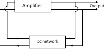
(3) An oscillator may be considered as amplifier which provides it's own input signal.
(4) The essential of a transistor oscillator are
(i) Tank circuit : Parallel combination of L and C. This network resonates at a frequency \[{{\nu }_{0}}=\frac{1}{2\pi }\sqrt{\frac{1}{LC}}\].
(ii) Amplifier : It receives dc power from the battery and converts into ac power. The amplifier increases the strength of oscillations.
(iii) Feed back circuit : This circuit supplies a part of the collector energy to the tank circuit.
(5) A basic common-emitter NPN oscillator is shown in the figure.
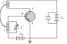
A tank circuit (L-C circuit) is connected in the base-emitter circuit, in which the capacitance C is kept variable. By changing C oscillations of a desired frequency can be obtained. An inductance coil L' connected in the collector-emitter circuit is coupled to coil L.
On completion of the circuit electrical oscillations are developed in the tank circuit. The circuit amplifies these oscillations. A part of the amplifies signal in the collector circuit is fed back in the base circuit by the coupling between L and L'. Due to this feed back amplitude of oscillation builds up till power dissipation in the oscillatory circuit becomes equal to power fed-back. In this state the amplitude of oscillations becomes constant. The oscillations can be transferred to an external circuit by mutual induction in a coil connected in that circuit.
(6) Need for positive feedback : The oscillations are damped due to the presence of some inherent electrical resistance in the circuit. Consequently, the amplitude of oscillations decreases rapidly and the oscillations ultimately stop. Such oscillations are of little practical importance. In order to obtain oscillations of constant amplitude, we make an arrangement for regenerative or positive feedback from the output circuit to the input circuit so that the losses in the circuit can be compensated.

Comparison between CB, CE and CC amplifier
| Characteristic | Amplifier | ||
| CB | CE | CC | |
| Input resistance \[({{R}_{i}})\] | \[\approx 50\] to \[200\,\,\Omega \] low | \[\approx 1\] to \[2\,\,k\Omega \]medium | \[\approx 150-800\,\,k\Omega \] high |
| Output resistance \[({{R}_{o}})\] | \[\approx 1-2\,\,k\Omega \] high | \[\approx 50\,\,k\Omega \] medium | \[\approx \,\,k\Omega \] low |
| Current gain | \[0.8-0.9\] low | \[20-200\] high | \[20-200\] high |
| Voltage gain | Medium | High | Low |
| Power gain | Medium | High | Low |
| Phase difference between input and output voltages | Zero | \[{{180}^{o}}\] | Zero |
| Used as amplifier for | current | Power | Voltage |


You need to login to perform this action.
You will be redirected in
3 sec

