Fluid Mechanics and Machinery
Category : Railways
Fluid Mechanics and Machinery
Fluid: Fluid is a substance which has the property tendency to flow under the action of shear and tangential forces.
Liquids and gases both are fluids.
Ideal and Real fluids:
Classification of fluids:
Fluids can be classified on the basis of the following:
Based on density and viscosity
(i) Ideal fluid: An ideal fluid is described as a fluid which is in compressible and also has zero viscosity and constant density.
(ii) Real fluids: A real fluid is described as a fluid which is compressible and viscous by nature. The density of real fluid are variable and while in motion, an amount of resistance is always offered by these fluids.
(iii) Newtonian fluids: Newtonian fluidss are denned as fluids those obey Newton's law of viscosity. The density of these fluids may be constant or variable. The viscosity is calculated according to Newton'.s law of viscosity as:
\[\tau =\mu \frac{du}{dy}\]
where, \[\tau \]=shear stress
\[\mu =\]viscosity of fluid
\[du/dy=\]velocity gradient
Examples are, water, ethyl alcohol, benzene etc.
(iv) Non – Newtonion fluids: Non-newtonian fluids are defined as fluids those do not obey Newton's laws of viscosity.
The density of these fluids may be constant or variable and the viscosity of these fluids does not remain constant.
Examples are Gels, Solutions of polymers, pastes etc.
(v) Compressible fluids: A compressible fluid is defined as the fluid which reduces its volume when an external pressure is applied. All the fluids available in nature are compressible.
(vi) In–compressible fluids: Incompressible fluids are defined as the fluids whose density does not change when the value of pressure changes. There is no effect of pressure on the density of fluid. In these fluids, density remains constant and viscosity remains non-zero.
(vii) Inviscid fluid: Inviscid fluid is the fluid which has zero iscosity and density may be constant or variable.
FLUID PROPERTIES
\[\rho =\frac{m}{V}\]
\[\omega =\frac{mg}{V}=\rho g\]
It may also be defined as the ratio of specific weight of the fluid to the standard weight of fluid.
\[\text{Sg=}\frac{\text{weogjt}\,\,\text{of}\,\,\text{fluid}}{\text{weight}\,\,\text{of}\,\,\text{standard}\,\,\text{fluid}}\]
\[\text{Sg=}\frac{\text{Density}\,\,\text{of}\,\,\text{fluid}}{\text{Density}\,\,\text{of}\,\,\text{standard}\,\,\text{Fluid}}\]
Ex: oil of Sg of 0.8\[\Rightarrow {{\rho }_{oil}}=800\,\,kg/{{m}^{3}}\]
Specific volume (v):
It is expressed as the volume per unit mass of fluid.
\[v=\frac{V}{m}=\frac{1}{\rho }\]
Hydrostatic law: It states that rate of increase of pressure in a vertical direction is equal to weight density of fluid at that point.
Mathematically, pressure head (h)\[(h)=\frac{\rho }{\rho g}\]
\[\beta =\frac{-\frac{dV}{V}}{dp}=\frac{1}{\rho }\,\,\frac{d\rho }{dp}\]
Liquids are highly incompressible.\[\therefore \,\frac{d\rho }{dp}=0\]
Gases are highly compressible as \[P\propto \rho \]
It is defined as reciprocal of compressibility.
VISCOSITY
It is the property of fluid by virtue of which one layer resists the motion of another adjacent layer, i.e. its résistance to shearing stresser.
Newton's Law of Viscosity
The viscous shear stress between two layers at a distance 'y' from the surface can be written as: \[\tau \propto \frac{du}{dy}\]
as \[\tau =\mu \frac{du}{dy}\]
Kinematic Viscosity (v)
It is expressed as the ratio of dynamic viscosity (p.) and density of fluid\[(\rho )\].
\[v=\frac{\mu }{\rho }\]
Units \[SI\to {{m}^{2}}/s\]
\[CgS\to Stokes/c{{m}^{2}}/s\]
\[1\,\,stokes={{10}^{-4}}{{m}^{2}}/s\]
Effect of temperature and pressure on viscosity:
SURFACE TENSION \[(\sigma )\]
Cohesive and Adhesive forces:
Cohesive forces are intermolecular attraction of forever between molecular of same liquid/fluid.
Adhesive forces are attractive forces between the molecular of a liquid/fluid and the molecular of a solid boundary surface in contact.
CAPILLARITY
When a tube of very fine diameter is immersed in a liquid, there will be rise or fall of liquid level in the tube depending upon whether the liquid is wetting with the tube or non-wetting.
The rise or fall of liquid level in the tube is a phenomenon known as capillarity.
h: rise of liquid level in tube
\[\sigma \]: surface tension
r: radius of capillary tube
\[\rho \]: density of liquid
\[\theta \]: angle of contact
\[\left[ h=\frac{2\sigma \cos \theta }{\rho gr} \right]\]
For an annular capillary having external radius\[{{r}_{1}},\]
\[\left[ h=\frac{2\sigma \cos \theta }{\rho g({{r}_{2}}-{{r}_{1}})} \right]\]
Pascal's law: It states that pressure intensity at any point in a liquid of rest, is same in all directions. If\[{{P}_{x}}\],\[{{P}_{y}}\]and \[{{P}_{Z}}\]are the pressure in x, y & z - direction acting on a fluid element, at rest, then
\[{{P}_{x}}={{P}_{y}}={{P}_{Z}}\]
PRESSURE MEASUREMENT DEVICES
III. MANOMETER
FLUID STATICS
In fluid statics, the behaviour or characteristics of the fluid is studied when the fluid is at rest
\[\to \] Pressure is described as the normal force applied by a fluid/ unit area. The unit of pressure N/m2 which is also termed as Pascal.
\[\to \] In case of a fluid, Pressure acts in all the directions. In static liquid. The value of pressure increases with the increasing depth.
\[\to \] At any point in a fluid, pressure is directly proportional to the fluid density and depth in the fluid.
Pressure (P) \[\frac{\rho AHg}{A}=\rho Hg\]
hence from the above expression,
\[\rho \propto \rho \,\,and\,\,\rho \propto H\]
\[\to \] The pressure of fluid is equal in all directions at any specific depth of the fluid.
\[\to \] Fluid pressure does not depend on the shape or area of the container. Pressure is a scalar quantity a. s it has only megnitude but no direction.
Atmospheric Pressure
Atmospheric pressure is defined as the normal pressure exerted by the atmospheric air on the surfaces which are in contact with air.
Gauge Pressure
Gauge pressure is defined as the difference between the absolute pressure and the pressure exerted by the atmosphere i.e. atmospheric pressure.
Absolute Pressure
Absolute pressure is defined as the sum of fluid pressure and atmospheric pressure. It is an actual pressure at a given specific point.
Vacuum Pressure
Vacuum pressure is defined as the pressure which is below the atmospheric pressure.
Relations Among Different Kinds of Pressures
Let, \[{{P}_{atm}}\] Atmospheric pressure
\[{{P}_{abs}}=\]Absolute pressure
\[{{P}_{gause}}=\]Gauge pressure
\[{{P}_{vac}}=\]Vacuum pressure
\[\left[ {{P}_{abs}}={{P}_{atm}}+{{P}_{gauge}} \right]\]
\[\left[ {{P}_{vac}}={{P}_{atm}}+{{P}_{abs}} \right]\]
FLUIDKINEMATICS
Different Types of Flow
If the properties in the flow are not changing with respect to time, such a flow is known a steady flow.
If the properties (velocity at any given time) is not changing with respect to space, such a flow is known as uniform flow.
If the density of the fluid doesn't change with respect to pressure, the flow is known as incompressible flow.
If the fluid particles are rotating about their centre of mass, the flow is known as rotational flow. If the fluid particles aren't rotating about their centre of mass, the flow is known as irrotational flow.
\[\to \] In case of an internal flow, it is surrounded or boundedby solid boundaries. Due to these solid boundaries thedevelopment of boundary layer is restricted.
\[\to \] In case of external flow, the fluid flows over the bodies which are immersed in an un-bounded fluid and hence the boundary layer develops freely in single direction.
Eg: flows over air foild, turbine blades etc.
Euler's Equation of Motion
The Euler's equation considers the following assumptions
![]() Euler's\[{{E}^{eq}}\]for steady flow
Euler's\[{{E}^{eq}}\]for steady flow
Integrating the above equation. We obtain Bernoulli's equation
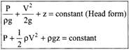
For Bernoulli's equation, there are two more assumptions i.e.
Under the five assumptions stated above, the summation of all energies (Pressure, Kinetic and Potential) per unit volume remains constant at each and every point in a flow.
FLOW THROUGH BRANCHED PIPES
Pipes in Series
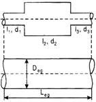
\[Q={{Q}_{1}}={{Q}_{2}}={{Q}_{3}}\]
\[{{h}_{f}}={{({{h}_{f}})}_{1}}+{{({{h}_{f}})}_{2}}+{{({{h}_{f}})}_{3}},\]
\[\Rightarrow h=\frac{4t}{2g}\left( \frac{{{L}_{1}}V_{1}^{2}}{{{d}_{1}}}+\frac{{{L}_{2}}V_{2}^{2}}{{{d}_{2}}}+\frac{{{L}_{3}}V_{3}^{2}}{{{d}_{3}}} \right)\]
Dupit's Equation
A pipe of uniform diameter is said to be equivalent to compound pipe if it carries same discharge and encounters same losses.
![]()
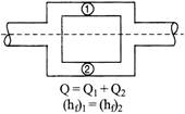
PIPES IN PARALLEL
In parallel arrangement, head losses remain same but discharge gets divided.
POWER TRANSMISSION THROUGH PIPE
\[{{P}_{theoretical}}=\rho QgH\]
\[{{P}_{actual}}=\rho Q\,(H-{{h}_{f}})\]
Where\[{{h}_{f}}\]are the head losses in pipe
\[\eta =\frac{\rho \,Q\,(H-{{h}_{f}})}{\rho \,Q\,\,gH}\]
For maximum efficiency ![]()
TURBULENT FLOWS
\[\tau =\rho u'v'=\rho {{1}^{2}}{{\left( \frac{du}{dy} \right)}^{2}}\]
\[\tau =\]turbulent shear stress
\[l=\]mixing length, \[l=\]0.4 y, y is distance from pipe wall Mixing length is the length in transverse direction where in fluid particles after colliding loose excess momentum and reach the momentum as of local environment.
\[{{V}_{*}}:Shear\,\,velocity\,\,{{V}_{*}}=\sqrt{\frac{\tau }{\rho }}\]
\[y'=\delta '/{{10}^{7}}(for\,\,smooth\,\,pipes)\]
\[y'=k/30(for\,\,rough\,\,pipes)\]
\[{{R}_{eR}}=\frac{{{V}_{*}}K}{v}\]
\[{{R}_{eR}}>100\Rightarrow rough\,pipe\]
\[{{R}_{eR}}<4\Rightarrow smooth\,\,pipe\]
\[4<{{R}_{eR}}<100\Rightarrow transition\]
TURBOMACHINERY
The conversion of energy carried by water into electrical energy is carried out by the turbo-generator. In this a rotating turbine driven by the water and connected by a common shaft to the rotor of a generator.
Any turbine consists of a set of curved blades designed to deflect the water in such a way that it gives up as much as possible of its energy. The blades and their support structure make up the turbine runner, and the water is directed on to this either by channels and guide vanes or through a jet, depending on the type of turbine.
The efficiency of any turbo machine
\[\eta =\frac{P(power\,\,output)}{1000\times Q\times g\times H(Power\,\,input)}\]
where, Q=flow rate of the falling water the number of cubic metres per second
g = acceleration due to gravity
H = effective head
Mass of a cubic metre of fresh water = 1000 kg
\[\therefore \] mass falling per second \[=1000\times Q\]
Hydraulic Turbines
In hydraulic turbines, the conversion of hydraulic energy into mechanical energy takes place. This mechanical energy is utilized for running an electrical generator which is directly connected with the shaft of the hydraulic turbine. Thus, finally, the conversion of mechanical into electrical energy takes place.
Classification of Hydraulic Turbines
The hydraulic turbines are classified based on the following basis:
\[\to \] Based on the type of energy at inlet
(a) Impulse turbines
(b) Reaction turbines
\[\to \] Based on the direction of flowing water
(a) Tangential flow turbines
(b) Axial flow turbines
(c) Radial flow turbines
(d) Mined flow turbines
\[\to \]Based on the Head of water and water quantity available
(a) High head and small quantity of flowing water
(b) Medium head and small quantity of flowing water
(c) Low head and larger quantity of flowing water
\[\to \]Based on the specific speed of the turbine
(a) Low specific speed turbine (specific speed < 60)
(b) Medium specific speed turbine (specific speed: 60 to 400)
(c) High specific speed turbine (specific speed : above 400)
Comparison between Impulse Turbine and Reaction Turbine
|
Impulse turbine |
Reaction turbine |
|
(i) In this, the conversion of potential energy into kinetic energy takes place by nozzle before entering to turbine |
(i) A part of energy of fluid is converted into kinetic energy before entering the fluid into turbine. |
|
(ii) There are no losses in flow regulations |
(ii) There are losses in flow regulations |
|
(iii) The whole unit is placed above the tailrace |
(iii) The whole unit is submerged in water below tailrace |
|
(iv) Blades are in acting mode only when they are in front of nozzle |
(iv) Blades are in acting mode at all the time |
FRANCIS TURBINE
Francis turbines are by far the most common type in present-da'. medium or large-scale plants. They are used in installations whers the head is as low as two metres or as high as 300. These are radial-flow turbines.
Francis turbine is completely submerged, it can run equally well with its axis horizontal or vertical.
Francis turbines are most efficient when the blades are movrng nearly as fast as the water, so high heads imply high speeds rotation.
The range of specific speeds,\[\left( {{N}_{S}}=n\times \sqrt{\frac{P}{{{H}^{2}}\times \sqrt{H}}} \right)\] for Francis turbine is \[70-500.\]
Main parts of a Francis turbine:
(a) Penstock (b) Spiral casing
(c) Guide vanes (d) Runner
(e) Draft tube
KAPLAN TURBINES
Kaplan turbine is a axial flow or propeller type turbine which has adjustable blades. It is an inward flow reaction turbine, i.e., the working fluid changes pressure as it moves through the turbine and gives up its energy.
Main parts of a kaplan turbine:
(a) Scroll casing (b) Guide vanes
(c) Stay ring (d) Runner blades
(e) Draft tube
Unit Quantities
The unit quantities provide the speed, discharge and power for a particular turbine by keeping the head of 1 m (assumed) considering the same efficiency unit quantities provide a suitable information regarding the prediction of performance of turbines.
(a) Unit speed \[({{N}_{u}})\]: The turbine speed working under unit head is known as unit speed
(b) Unit discharge\[({{Q}_{\mu }})\]: The turbine discharge working under unit head is known as unit discharge.
(c) Unit Power\[({{P}_{u}})\]: The turbine power produced while working under a unit head is known as unit power
\[{{P}_{u}}=\frac{P}{{{H}^{3/2}}}\]
Centrifugal Pumps
In centrifugal pumps, the conversion of mechanical energy into Hydraulic or pressure energy by the application of centrifugal force. The flow of water is in radial outward direction. The principle on which it works is forced vortex flow. Common applications are sewage, petroleum and petrochemical pumping.
\[\to \] Working principle: Centrifugal pumps work based on the principle of forced vortex flow in which rotation of a certain mass by the external torque rise in pressure head takes place. The energy is converted due to two main parts of the pump. i.e. impeller and casing. The driver energy is converted into kinetic energy by impeller and the kinetic energy is converted into the pressure energy by the diffuser.
Main Parts of Centrifugal Pump
A centrifugal pump consists of two main parts:
(a) Rotating components:
\[\to \] Impeller: It is the main rotating component which works for the purpose of providing centrifugal acceleration to the fluid.
\[\to \] Shaft: It works for the purpose of transmitting torques which are encountered during starting and during operation. It also works as a supporting member for the impeller and other rotating components.
(b) Stationary components:
\[\to \] Casing: In this, the conversion of kinetic energy into pressure energy takes place. Generally three kinds of casings are used given as:
\[\to \] Diffusers are employed in multistage pumps.
Classification of Centrifugal Pumps
Centrifugal pumps maybe classified based on the following:
(a) Based on working head
(b) Based on specific speed
(c) Based on types of casing
(d) Based on direction of flow of water
(e) Number of entrances to the impleller
(f) Based on disposition of the shaft
(g) Based on number of stages
Heads in Centrifugal Pumps
(a) Suction head; It is defined as the vertical height of centre line of the centrifugal pump, which is above the water surface, to the pump.
(b) Delivery head: It is defined as the distance between centre line of the centrifugal pump and the surface of water in the tank to which water is to be delivered.
(c) Static head: It is defined as the sum of suction head and delivery head.
(d) Manometric head: It is defined as the head against which work is done by the centrifugal pump.
Efficiencies
(a) Manometric efficiency: It is defined as the ratio of manometric head with the head provided by impleller.
\[{{\eta }_{mano}}=\frac{Manometric\,\,head({{H}_{m}})}{({{V}_{{{W}_{2}}}}{{u}_{2}})/g}\]
\[{{\eta }_{mano}}=\frac{{{H}_{m}}}{({{V}_{{{W}_{2}}}}{{u}_{2}})/g}\]
(b) Mechanical efficiency \[({{\eta }_{mech}})\]
It is defined as the ratio of power delivered by the impeller with the power input to shaft.
\[{{\eta }_{mech}}=\frac{(W{{V}_{{{W}_{2}}}}{{U}_{2}})/g}{{{\rho }_{s}}}\]
(c) Overall efficiency\[({{\eta }_{0}})\]: It is defined as the ratio of power output to power input to the pump or shaft.
\[{{\eta }_{0}}=\frac{w{{H}_{m}}}{P}\]
(d) Volumetric efficiency\[({{\eta }_{vol}})\]: It is defined as the ratio of actual discharge to the sum of actual discharge and rate of leakage.
\[{{\eta }_{vol}}=\frac{{{Q}_{A}}}{{{Q}_{A}}+{{Q}_{L}}}\]
where, \[{{Q}_{A}}=\]Actual discharge,\[{{Q}_{L}}=\]rate of leakage
(e) Hydraulic efficiency: It is defined as the ratio of manometric head to the theoretical head.
\[{{\eta }_{N}}=\frac{{{H}_{m}}}{{{H}_{T}}}\]


You need to login to perform this action.
You will be redirected in
3 sec

