Micro Processor and Computer Networks
Category : Railways
Micro Processor and Computer Networks
MICROCOMPUTER
A microcomputer has three basic blocks: a central processing unit (CPU), a memory unit, and an input/output unit.
The CPU executes all the instructions and performs arithmetic and logic operations on data. The CPU of the microcomputer is called the "microprocessor." The microprocessor is typically a single VLSI (Very Large-Scale Integration) chip that contains all the registers, control unit, and arithmetic/ logic circuits of the microcomputer.
A memory unit stores both data and instructions. The memory section typically contains ROM and RAM chips. The ROM can only be read and is nonvolatile, that is, it retains its contents when the power is turned off. A ROM is typically used to store instructions and data that do not change. For example, it might store a table of codes for outputting data to a display external to the microcomputer for turning on a digit from 0 to 9.
One can read from and write into a RAM. The RAM is volatile; that is, it does not retain its contents when the power is turned off. ARAM is used to store programs and data that are temporary and might change during the course of executing a program. An I/O (Input/Output) unit transfers data between the microcomputer and the external devices via I/O ports (registers). The transfer involves data, status, and control signals.
In a single-chip microcomputer, these three elements are on one chip, whereas with a single-chip microprocessor, separate chips for memory and 1/0 are required. Microcontrollers evolved from single-chip microcomputers. The microcontrollers are typically used for dedicated applications such as automotive systems, home appliances, and home entertainment systems. Typical microcontrollers, therefore, include on-chip timers and AID (analog to digital) and D/A (digital to analog) converters. Two popular microcontrollers are the Intel 8751 (8 bit)/8096 (16 bit) and the Motorola HC 11 (8bit)/HC16 (16bit). The 16-bit microcontrollers include more on-chip ROM, RAM, and I/O than the 8-bit microcontrollers. Figure above shows the basic blocks of a microcomputer. The System bus (comprised of several wires) connects these blocks.
MICROPROCESSOR
Architecture of 8085 Microprocessor
One includes ALU (arithmetic/logic unit) & an 8-bit regal (accumulator), instruction decoder & flags.
The other one includes 8-bit & 16-bit registers.
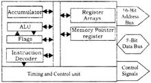
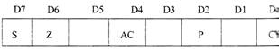
Fig. Flag register
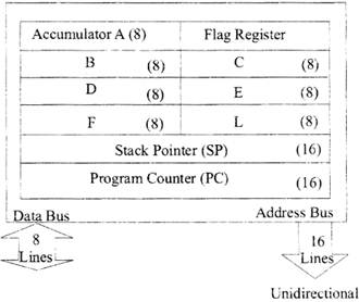
Registers
The 8085 programming model fig. includes six registers. accumulator, and one flag register, as shown in Figure. The 3 has six general-purpose registers to store 8 –bit data; these identified as B, C, D, E. H, and L as shown in the fig. They can combined as register pairs - BC, DE, and HL - to perform some bit operations. The programmer can use these registers to store or copy data into the registers.
Flags
The AL 17 includes five flip-flops, which are set or reset after an operation according to data conditions of the result in the accumulator and other registers. They are called Zero (Z), Carry Sign (S), Parity (P), and Auxiliary Carry (AC) flags; The most commonly used flags are Zero, Carry, and Sign. The microprocessor uses these flags to test data conditions.
For example, after an addition of two numbers, if the sum in the accumulator is larger than eight bits, the flip-flop uses to indicate a carry — called the Carry flag (CY) - is set to one. When an arithmetic operation results in zero, the flip-flop called the Zero (Z) flag is set to one. The flags are stored in the 8-bit register so that the programmer can examine these flags (data conditions) by accessing the register through an instruction.
Program Counter (PC)
This 16 – bit register deals with sequencing the execution of instrutions. This register is a memory pointer. Memory locations have 16 – bit addresses, and that is why this is a 16 – bit register.
The microprocessor uses this register to sequence the execution of the instructions. The function of the program counter is to point to the memory address from which the next byte is to be fetched. When a byte (machine code) is being fetched, the program counter is incremented by one to point to the next memory location.
Stack Pointer (SP)
The stack pointer is also a 16 – bit register used as a memory Pointer, It points to a memory location in R/'W memory, called the stock. The beginning of the stack is defined by loading 16 – bit address in the stack pointer.
Address bus is basically a group of 16 lines named from \[{{A}_{0}}\,\,to\,\,{{A}_{15}}\]is unidirectional in nature and helps in identifying a peripheral or memory location. Its structure is given in the fig.
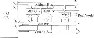
Fig. 8085 Bus structure
The address lines are split into two segments: \[{{A}_{15}}-{{A}_{8}}\And A{{D}_{7}}-A{{D}_{0}}\] are unidirectional & are used for higher order address & latter are bidirectional & are used for lower order address bus as well as data bus.
8085 Addressing Modes
The various formats for specifying operands are called the
ADDRESSING MODES For 8085, they are of various types are:
Example: MVI R, data
Example: MOV Rd. Rs
Example: IN 00H or OUT 01H
Instruction Word Size
The 8085 instruction set is classified into the following three groups according to word size:
Memory interfacing:
While executing an instruction, there is a necessity for the microprocessor to access memory frequently for reading various instruction codes and data stored in the memory. The interfacing circuit aids in accessing the memory.
Memory requires some signals to read from and write to registers. Similarly the microprocessor transmits some signals for reading or writing a data.
The interfacing process involves matching the memory requirements with the microprocessor signals. The interfacing circuit therefore should be designed in such a way that it matches the memory signal requirements with the signals of the microprocessor. For example for carrying out a READ process, the microprocessor should initiate a read signal which the memory requires to read a data. In simple words, the primary function of a memory interfacing circuit is to aid the microprocessor in reading and writing a data to the given register of a memory chip.
I/O Interfacing:
We know that keyboard and Displays are used as communication channel with outside world. So it is necessary that we interface keyboard and displays with the microprocessor. This is called I/O interfacing. In this type of interfacing we use latches and buffers for interfacing the keyboards and displays with the microprocessor.
But the main disadvantage with this interfacing is that the microprocessor can perform only one function. It functions as an input device if it is connected to buffer and as an output device if it is connected to latch. Thus the capability is very limited in this type of interfacing.
DATATRANSFER SCHEMES IN A
MICROPROCESSOR
Data transfer schemes
are dependent on on-line or off-line processing, type of I/O device (capable of parallel or serial data transfer, synchronous or asynchronous) and the particular application-Data transfer schemes may toe categorized into parallel data transfer and serial data transfer.
Parallel “ucp” data transfer
In parallel data transfer, a group of bits (for example 8–bits) are transmitted from one device to another at any time. To achieve parallel data transfer, a group of data lines will be conducting the processor and peripheral devices. Normally in microprocessor based system the parallel data transfer schemes are adopted to transfer data between various devices inside the system. Parallel data transfer is impractical over long distances because of the prohibitive cost of installing a large number of lines.
Serial Data Transfer
In serial data transfer, each bit of the word is sent in succession, one at a time over a single pair of wires. A parallel to serial converter is used to convert the incoming parallel data to a serial form and then the data is sent out with the least significant bit DO first and the most significant bit D7 last.
Addressing Modes:
The different ways in which the location of an operand is specified in an instruction are referred to as addressing modes.
Types of Addressing Modes
Types of Instructions
Typical Data Transfer Instructions
|
Name |
Mnemonic |
|
Load |
LD |
|
Store |
ST |
|
Move |
MOV |
|
Exchange |
XCH |
|
Input |
IN |
|
Push |
OUT |
|
Pop |
PUSH |
|
POP |
POP |
(i) Typical Arithmetic Instructions Ex: INC, DEC, ADD, SUB, MUL, DIV, ADDC, SUBB, NEG
(ii) Typical Logical and Bit Manipulation Instructions Ex: CLR. COM, AND, OR, XOR, CLRC, SETC, COMC, El, DI.
(iii) Typical Shift Instructions Ex: SHR. SHL. ROR, ROL.
Program Control Instructions
Program control instructions specify conditions for altering the content of the program counter, while data transfer and manipulation instructions specify conditions for data processing operations. The change in value of a program counter as a result of the execution of a program control instruction causes a break in the sequence of instruction execution.
Typical Program Control Instructions
|
Name |
Mnemonic |
|
BRANCH |
BR |
|
JUMP |
JMP |
|
SKIP |
SKP |
|
CALL |
CALL |
|
RETURN |
RET |
|
COMPARE |
CMP |
|
TEST |
TST |
Program Interrupt
The program interrupts are used to handle a variety of problems that arise out of normal program sequence.
Types of Interrupts
There are three major types of interrupts
Output (I/O) devices or from a timing device.
CPU.
I/O INTERFACE (INTERRUPT AND DMA MODE)
Peripheral Devices
Input-Output Interface
I/O communication
(a) Data formats of internal memory of CPU and the peripheral devices (I/O devices) are different.
(b) Data transfer rates CPU and the I/O devices are different.
Asynchronous Data Transfer
Handshaking
Synchronous Data Transfer
In synchronous data transfer a global or shared clock is provided to both sender and receiver. The sender and receiver works simultaneously.
Modes of Transfer
The information from external device is stored in memory. Information transferred from the central computer into an external device via memory unit. Hence, this data transfer between the central computer and I/O devices is handled in various modes.
Programmed I/O: In this mode, each data item is transferred by an instruction in the program. The CPU issues a command then waits for I/O operations to be complete. As the CPU is faster than the I/O module, the problem with programmed I/O is that the CPU has to wait a long time for the
I/O module of concern to be ready for either reception or transmission of data.
Programmed I/O basically works in these ways:
The CPU, while waiting, must repeatedly check the status of the I/O module, and this process is known as Polling. As a result, the level of the performance of the entire system is severely degraded.
Interrupt-initiated I/O: This mode removes the drawback of the programmed I/O mode. The CPU issues commands to the I/O module then proceeds with its normal work until interrupted by I/ O device on completion of its work.
For input, the device interrupts the CPU when new data has arrived and is ready to be retrieved by the system processor. The actual actions to perform depend on whether the device uses I/O ports, memory mapping.
For output, the device delivers an interrupt either when it is ready to accept new data or to acknowledge a successful data transfer.
Memory-mapped and DMA-capable devices usually generate interrupts to tell the system they are done with the buffer.
Although Interrupt relieves the CPU of having to wait for the devices, but it is still inefficient in data transfer of large amount because the CPU has to transfer the data word by word between I/O module and memory.
Below are the basic operations of Interrupt:
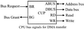
Direct Memory Access (DMA)
Direct Memory Access (DMA) means CPU grants I/O module authority to read from or write to memory without involvement.
DMA module controls exchange of data between main memory and the I/O device. Because of DMA device can transfer data directly to and from memory, rather than using the CPU as an intermediary, and can thus relieve congestion on the bus. CPU is only involved at the beginning and end of the transfer and interrupted only after entire block has been transferred.
The CPU initiates the transfer by supplying the interface with the starting address and the number of words needed to be transferred and then proceeds to execute other tasks. When the transfer is made, the DMA requests memory cycles through the memory bus. When the request is granted by the memory controller, the DMA transfers the data directly into memory.
The Bus Request (BR) input is used by the DMA controller to request the CPU to get the control of buses. When this input is active, the CPU terminates the execution of the current instruction and places the address bus and the data bus. The CPU activates the Bus Grant (BG) output to inform the external DMA that the buses are available. The DMA now takes the control of the buses to conduct the memory transfer. When DMA terminates the transfer, it disables the bus request line. The CPU disables the bus grant, takes the control of the buses.
DATA COMMUNICATION
It refers to the exchange of data between a source and a receiver. Data communication is said to be local if communicating devices are in the same building or a similarly restricted geographical area.
Datum mean the facts information statistics or the like derived by calculation or experimentation. The facts and information so gathered are processed in accordance with defined systems of procedure. Data can exist in a variety of forms such as numbers, text, bits and bytes. The Figure is an illustration of a simple data communication system.
![]()
A data communication system may collect data from remote locations through data transmission circuits, and then outputs processed results to remote locations. Figure provides a broader view of data communication networks. The different data communication techniques which are presently in widespread use evolved gradually either to improve the data communication techniques already existing or to replace the same with better options and features. Then, mere are data communication jargons to contend with such as baud rate, modems, routers, LAN, WAN, TCP/IP. ISDN, during the selection of communication systems.
Hence, it becomes necessary to review and understand these terms and gradual development of data communication methods.
ISO/OSI MODEL IN COIVSMUNSCATION NETWORKS
The ISO-OSI model is a seven layer architecture. It defines seven layers or levels in a complete communication system.
Functions of Different Layers
Layer 1: The Physical Layer:
Layer 2: Data Link Layer:
Layer 3: The Network Layer:
Layer 4: Transport Layer:
Layer 5: The Session Layer;
Layer 6: The Presentation Layer:
Layer 7: Application Layer:
MODEM
Modem is abbreviation for Modulator - Demodulator. Modems are used for data transfer from one computer network to another computer network through telephone lines. The computer networks in digital mode, while analog technology is used for carrying massages across phone lines.
The transmission medium between the two modems can be dedicated circuit or a switched telephone circuit. If a switched telephone circuit is used, then the modems are connected to the local telephone exchanges. Whenever data transmission is required connection between the modems is established through telephone exchanges.
TYPES OF MODEMS
Asynchronous & Synchronous Modems
Asynchronous Modem
Synchronous Modem
Modulation techniques used for Modem:
The basic modulation techniques used by a modem "to convert digital data to analog signals are:
These techniques are known as the binary continuous wave (CW) modulation.
Modems are always used in pairs. Any system whether simplex, half duplex or full duplex requires a modem at the transmitting as well as the receiving end.
Thus a modem acts as the electronic bridge between two worlds - the world of purely digital signals and the established analog world.
TCP/IP
Short for Transmission Control Protocol/Internet Protocol, TCP/IP is a set of rules (protocols) governing communications among all computers on the Internet. More specifically. TCP/IP dictates how information should be packaged (turned into bundles of information called packets), sent, and received, as well as how to get to its destination.
Three of the most common TCP/IP protocols
Domain names and TCP/IP addresses
The TCP/IP address for a website or web server is typically not easy to remember. To remedy this issue, a domain name is used instead. For example, 45.79.151.23 is the IP address for the Computer Hope website and computerhope.com is the domain name.
Using this method, instead of a set of numbers, makes it much easier for users to remember Computer Hope's web address.
ISDN
ISDN is a circuit-switched telephone network system, that also provides access to packet switched networks, designed to allow digital transmission of voice and data over ordinary telephone copper wires, resulting in better voice quality than- an analog phone. It offers circuit-switched connections (for either voice or data), and packet-switched connections (for data), in increments of 64 Kbit/s.
ISDN Interfaces
There are several kinds of access interfaces to the ISDN dermed:
Basic Rate Interface (BR1)
Primary Rate Interface (PR1)
Broadband-ISDN (B-ISDN)
ISDN Services
The purpose of the ISDN is to provide fully integrated digital services to users. These services fall into categories- better services, teleservices and supplementary services.
Bearer services belong to the first three layers of the OSI model and are well defined in the ISDN standard. They can be provided using circuit-switched, packet-switched, frame switched, or cell-switched networks.
LAN (LOCAL AREA NETWORK)
LAN looks like an acronym that a board of directors spent a lot of money and time trying to create, but it actually stands for any generic local area network. A network is a group of and other devices connected together so they can pass back and forth.
The data rates for LAN range from 4 to 16 Mbps with the maximum of 100 Mbps.
The components used by LANs can be divided into cabling standards, hardware, and protocols. Various LAN protocols are
Ethernet, Token Ring: TCP/IP, 5MB, NetBIOS and Net Beui, IPX SPX, Fiber Distributed Data Interchange (FDDI) and Asynchronous Transfer Mode (ATM).
LAN topologies
Various topologies are possible for the broadcast LANs such as bus topology or ring topology.
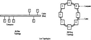
Bus topology


You need to login to perform this action.
You will be redirected in
3 sec

