Production Engineering
Category : Railways
Production Engineering
PRODUCTION TECHNOLOGY
Technology is the process of applying the finding of science and other forms of enquiry to applied situations. Production technology therefore involves applying the work of researchers to develop new products and processes.
Production Engineering
Manufacturing or Production Engineering is the subset / specialization of a Mechanical Engineering. Mechanical
Engineering with the focus only on Machine Tools, Materials Science, Tribology, and Quality Control is known as Manufacturing Engineering. Professional manufacturing engineers are responsible for all aspect of the design, development, implementation, operation and management of manufacturing system. Manufacturing is the most important element in any engineering process & Manufacturing Engineers are key personnel in many organization. The manufactured products range from aero planes, turbines, engines and pumps to integrated circuits and robotic equipment.
What does a Production Engineer do?
Production Engineers work towards Choosing machinery and equipments for the particular manufacturing process
Production Engineers will be planning & scheduling the production in any manufacturing industry.[E.g. Automobile Manufacturing industry].
Production Engineers will be programming the CNC machines to produce engineering components such as gears, screws, bolts, etc
They are responsible for quality control, distribution and inventory control.
Top Sectors for Production Engineers to work
Production Engineering covers two domains:
(a) Production or Manufacturing Processes
(b) Production Management
(a) Manufacturing Processes:
This refers to science and technology of manufacturing products effectively, efficiently, economically and environment-friendly through
All such manufacturing processes, systems, techniques have to be
(b) Production Management:
This is also equally important and essential in the manufacturing world. It mainly refers to planning, coordination and control of the entire manufacturing in most profitable way with maximum satisfaction to the customers by best utilization of the available resources like man, machine, materials and money. It may be possible to manufacture a product of given material and desired configuration by several processes or routes as schematically indicated in Fig. below Processes Input (raw material) Output (product)
Processes
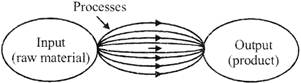
Fig: Possibility of manufacturing in number of routes.
Broad classification of Engineering Manufacturing
Processes:
It is extremely difficult to tell the exact number of various manufacturing processes existing and are being practiced presently because a spectacularly large number of processes have been developed till now and the number is still increasing exponentially with the growing demands and rapid progress in science and technology. However, all such manufacturing processes can be broadly classified in four major groups as follows:
(a) Shaping or forming Manufacturing a solid product of definite size and shape from a given material taken in three possible states: in solid state - e.g., forging rolling, extrusion, drawing etc in liquid or semi-liquid state - e.g., casting, injection molding etc. in powder form - e.g., powder metallurgical process.
(b) Joining process: Welding, brazing, soldering etc.
(c) Removal process: Machining (Traditional or Non- traditional), Grinding etc.
(d) Regenerative manufacturing Production of solid products in layer by layer from raw materials in different form:
Manufacturing is the latest one which is generally accomplished very rapidly and quite accurately using CAD and CAM for Rapid
Prototyping and Tooling.
(a) Machining Purpose:
Purpose of Machining Most of the engineering components such as gears, bearings, clutches, tools, screws and nuts etc. need dimensional and form accuracy and good surface finish for serving their purposes.
Performing like casting, forging etc. generally cannot provide the desired accuracy and finish. For that such preformed parts, called blanks, need semi-finishing and finishing and it is done by machining and grinding. Grinding is also basically a machining process.
Machining to high accuracy and finish essentially enables a product
fulfill its functional requirements
improve its per formaace
prolong its service
(b) Principle of Machining:
The basic principle of machining is typically illustrated in Fig, below:
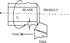
Fig: Principle of machining (turning)
A metal rod of irregular shape, size and surface is converted into a finished rod of desired dimension and surface by machining by proper relative motions of the tool-work pair.
(c) Definition of Machining:
Machining is an essential process of finishing by which jobs are produced to the desired dimensions and surface finish by gradually removing the excess material from the preformed blank in the form of chips with the help of cutting tool(s) moved past the work surface(s).
METALLURGICALPRODUCTTON-TECHNOLOGY
Metallurgy is a domain of materials science and engineering that studies the physical and chemical behavior of metallic elements, their inter-metallic compounds, and their mixtures, which are called alloys. Metallurgy is also the technology of metals: the way in which science is applied to the production of metals, and the engineering of metal components for usage in products for consumers and manufacturers. The production of metals involves the processing of ores to extract the metal they contain, and the mixture of metals, sometimes with other elements, to produce alloys. Metallurgy is distinguished from the craft of metalworking, although metalworking relies on metallurgy, as medicine relies on medical science, for technical advancement. The science of metallurgy is subdivided into chemical metallurgy and physical metallurgy.
Metallurgy is subdivided into ferrous metallurgy (also known as black metallurgy) and non-ferrous metallurgy (also known as colored metallurgy). Ferrous metallurgy involves processes and alloys based on iron while non-ferrous metallurgy involves processes and alloys based on other metals. The production of ferrous metals accounts for 95 percent of world metal production.
BASIC MACHINE TOOLS
Machine tools are kind of machines on which metal cutting or metal forming processes are carried out.
Material removal is essentially done on machine tools, which may be Lathe, Milling, Drilling, Shaping, Planning, Broaching and Grinding machines.
There are hundreds of varieties of metal machine tools, ranging in size from small machines mounted on workbenches to huge production machines weighing several hundred tons, are used m modem industry. They retain the basic characteristics of their
19th- and early 20th-century ancestors and are still classed as one of the following:
Machine-Tool Characteristics
All machine tools must provide work-holding and tool-holding devices and means for accurately controlling the depth of the cut. The relative motion between the cutting edge of the tool and the work is called the cutting speed; the speed in which uncut material is brought into contact with the tool is called the feed motion. Means must be provided for varying both.
Because an overheated tool may lose its cutting ability. Temperatures must be controlled. The amount of heat that is generated depends on the shearing force and the cutting speed. Because the shearing force varies with the material being cut and the tool material varies in its tolerance for high temperatures, the optimum cutting speed depends both on the material being cut and the cutting-tool material. It is also influenced by the rigidity of the machine, the shape of the work piece, and the depth of the cut
Tool materials
In order to remove chips from a work-piece, a cutting tool must be harder than the work-piece and must maintain a cutting edge at the temperature produced by the friction of the cutting action.
Carbon steel
Steel with a carbon content ranging from 1 to 1.2 percent was the earliest material used in machine tools. Tools made of this carbon steel are comparatively inexpensive but tend to lose cutting ability at temperatures at about \[400{}^\circ \text{ }F\,\,\left( 205{}^\circ \text{ }C \right).\]
High-speed steel
In 1900 the introduction of high-speed steel permitted the operation of tools at twice or three times the speeds allowable with carbon steel, thus doubling or trebling the capacities of the world's machine shops. One of the most common types of high-speed steel contains 18 percent tungsten, 4 percent chromium, 1 percent vanadium, and only 0.5 to 0.8 percent carbons.
Cast alloys
A number of cast-alloy cutting-tool materials have been developed; these nonferrous alloys contain cobalt, chromium, and tungsten and are particularly effective in penetrating the hard skin on cast iron and retaining their cutting ability even when red hot.
Cemented tungsten carbide
This material was first used for metal cutting in Germany in 1926. Its principal ingredient is finely divided tungsten carbide held in a binder of cobalt; its hardness approaches that of a diamond.
Tungsten carbide tools can be operated at cutting speeds many times higher than those used with high-speed steel.
Oxides
Ceramic, or oxide, tool tips are one of the newest developments in cutting-tool materials. They consist primarily of fine aluminum oxide grains, which are bonded together.
Diamonds
Diamonds have been used for many years for truing grinding wheels, in wire-drawing dies, and as cutting tools. For cutting applications they are used largely for taking light finishing cuts at high speed on hard or abrasive materials and for finish-boring bronze and Babbitt-metal bearings.
Cutting tool Parameters:
Cutting Speed: Cutting speed is the distance traveled by the work surface in unit time with reference to the cutting edge of the tool. The cutting speed, v is simply referred to as speed and usually expressed in m/min.
Feed: The feed is the distance advanced by the tool into or along the work-piece each time the tool point passes a certain position in its travel over the surface. In case of turning, feed is the distance that the tool advances in one revolution of the work-piece. Feed is usually expressed in mm/rev. Sometimes it is also expressed in mm/min and is called feed rate.
Depth of cut: It is the distance through which the cutting tool is plunged into the work-piece surface. Thus it is the distance measured perpendicularly between the machined surface and the uncut surface or the previously machined surface of the work piece. The depth of cut d is expressed in mm.
Selection of cutting speed and feed:
The selection of cutting speed and feed is based on the following parameters:
DESIGN OF SINGLE POINT CUTTING TOOL
Design of single point cutting tool is an important aspect of tool engineering. This unit deals with the design of tool shank, design of single point cutting tool, and various forces involved during machining of the work-piece. Strength and rigidity of tool is also taken into account while designing single point cutting tool.
The basic elements of single point cutting tool are shown in figure below:
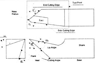
Figure: Single Point Cutting Tool
Figure: Single Point Cutting Tool
Symbol used in figure are:
\[{{\alpha }_{b}}-\]Back rake angle
\[{{\alpha }_{s}}-\]Side rake angle
\[{{\theta }_{e}}-\]End relief angle
\[{{\theta }_{s}}-\]Side relief angle
\[{{C}_{e}}-\]End cutting edge angle
\[{{C}_{s}}-\]Side cutting edge angle
Size: It is determined by the width of shank, height of shank and overall length.
Shank: Shank is main body of a tool. It is held in a holder.
Flank: Flank is the surface or surfaces below and adjacent to cutting edge.
Heel: Heel is intersection of the flank and base of the tool.
Base: Base is the bottom part of the shank. It takes the tangential force of cutting.
Face: Face is surface of tool on which chip impinges when separated from work-piece.
Cutting Edge: Cutting edge is the edge of that face which separates chip from the work-piece.
The total cutting edge consists of side cutting edge, the nose and end cutting edge.
Tool Point: That part of tool, which is shaped to produce the cutting edge and the face. The Nose It is the intersection of side cutting edge and end cutting edge.
Neck: Neck is the small cross section behind the point.
Side Cutting Edge Angle: The angle between side cutting edge and side of the tool shank is called side cutting edge angle. It is also called as lead angle or principle cutting angle.
End Cutting Edge Angle: The angle between the end cutting edge and a line perpendicular to the shank of tool is called end cutting edge angle.
DESIGN FOR CUTTING FORCES
The forces acting on the tool are an important aspect of machining. The knowledge of force is required for determination of power and also to design the various elements of machine tool, tool holders and fixtures. The cutting forces vary with the tool angle and accurate measurement of forces is useful in optimizing tool design. Dynamometers are capable of measuring tool forces with increasing accuracy. The component of forces acting on the rake face of tool, normal to the cutting edge is called cutting force, i.e. in the direction of line OY in Figure below:
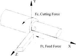
Figure: Forces acting on the Work-piece
METAL CASTING
Metal casting is a process in which molten metal is poured (in liquid state) into a mould. There molten metal acquires the desired shape and size. Which is made previously in the mould after some time when metal gets solidified it is removed from mould. Casting is the oldest method of shaping metal and non-metals. In earlier time most popular casting method was "Sand Casting" in which desired shape article is pressed in to sand and when the article removed from sand it leaves an impression or cavity in the sand. Which is exactly according to the shape of article after removal of article molten metal is poured in this cavity formed in the sand. The article used to make cavity in sand is known as pattern and the cavity made in sand is known as mould.
Advantage of Casting
Metal casting processes
Casting is one of the oldest manufacturing processes. It is the first step in making most of the products.
Steps: - Making mould cavity - Material is first liquefied by properly heating it in a suitable furnace. - Liquid is poured into a prepared mould cavity - allowed to solidify – product is taken out of the mould cavity, trimmed and made to shape we should concentrate on the following for successful casting operation:
(i) Preparation of moulds of patterns
(ii) Melting and pouring of the liquefied metal
(iii) Solidification and further cooling to room temperature
(iv) Defects and inspection
The six basic steps in making sand castings are,
(i) Pattern making,
(ii) Core making,
(iii) Moulding,
(iv) Melting and pouring,
(v) Cleaning
Pattern making - Replica of the part to be cast and is used to prepare the mould cavity. It is the physical model of the casting used to make the mould that made of either wood or metal. The mould is made by packing some readily formed aggregate material, such as moulding sand, surrounding the pattern. When the pattern is withdrawn, its imprint provides the mould cavity.
This cavity is filled with metal to become the casting. If the casting is to be hollow, additional patterns called 'cores' are used to form these cavities. Steps in making sand castings.
Core making
Cores are placed into a mould cavity to form the interior surfaces of castings. Thus the void space is filled with molten metal and eventually becomes the casting.
Moulding
Moulding is nothing but the mould preparation activities for receiving molten metal. Moulding usually involves:
(i) preparing the consolidated sand mould around a pattern held within a supporting metal frame, (ii) removing the pattern to leave the mould cavity with cores. Mould cavity is the primary cavity.
The mould cavity contains the liquid metal and it acts as a negative of the desired product. The mould also contains secondary cavities for pouring and channeling the liquid material in to the primary cavity and will act a reservoir, if required.
Melting and Pouring
The preparation of molten metal for casting is referred to simply as melting. The molten metal is transferred to the pouring area where the moulds are filled.
Cleaning
Cleaning involves removal of sand, scale, and excess metal from the casting. Burned-on sand and scale are removed to improve the surface appearance of the casting. Excess metal, in the form of fins, wires, parting line fins, and gates, is removed. Inspection of the casting for defects and general quality is performed.
Limitations of Metal casting processes
Dimensional accuracy and surface finish of the castings made by sand casting processes are a limitation to this technique.
Many new casting processes have been developed which can take into consideration the aspects of dimensional accuracy and surface finish. Some of these processes are die casting process, investment casting process, vacuum- sealed moulding process, and shell moulding process.
Metal casting is a labor intensive process.
CLASSIFICATION OF CASTING
(a) Sand Casting: In this process a cavity is made in a sand mold by using desired pattern and then after molten metal poured into mould. Which is after solidification known as casting. There are two main types of sand used for moulding
Green Sand and dry sand. In green sand un-bumed sand mixed with proper amount of clay as it binds and moistens and when the sand is mixed with binding material other than clay and moisture is known as Dry Sand.
Application of Sand Casting:
CASTING DEFECTS:
(i) Un- filled section: - This happens due to insufficient metal pouring at lower temperature than required.
(ii) Blow holes or porosity: - This defect happens, if molting temperature is too high and non -uniform cooling on the permeability of molding sand is low.
(iii) Shrinkage: - Some time after solidification the casting gets reduced in size at surface or internally which is known as shrinkage defect. Normally it happens due to improper cooling rate, improper gating, rising and type of material also.
(iv) Hot tears: - Too much shrinkage mostly causes cracks internally and on external surface known as hot tears. It happens due to improper cooling, and over ramming of molding sand, etc.
(v) Mis-Run: - When molten metal fails to reach at every section of mold then some sections remains un-filled known as mis run.
(vi) Cold shut: - When molten metal comes from two or more paths into the mould and during meeting these different flow
if not fuse together properly is known as cold shut.
(vii) Inclusions: - Any un-wanted metallic / non-metallic waste present in casting is known as inclusion thus inclusions may be slag of sand oxides or gases etc.
(viii) Cuts and washes: - These defects occurs due to erosion of sand from the mould or core surface by molten metal.
(ix) Shot metal: - This defect appears in the form of small metal shots embedded in the casting which are exposed on the fractured surface of the latter. It happens when the molten metal is poured into mould particularly when its temperature is relatively lower. It may splash the small particle separated from the main stream during the spray and thrown ahead and solidified quickly to form the shots.
Hot forging: Hot forging may be defined as a process in which metal is heated up to its plastic state and then a suitable external pressure is applied to achieve desired shape and size. The deformation of shape of metal depends on the type of force applied on it. If the force is applied along its length the cross-section will increase on the cost of reduction of its length. Similarly if the force is applied against its length the length will increase and the cross-sectional area will decrease.
Forging may be used to bend the work piece. Without change its length along with using suitable die- and punch etc. In forging process external force may be applied by hand hammer, power operated hammers, and presses etc. If the force applied by mannually by hammers this process is known as smithy process.
Classification of forging: Forging may be classified into following types
(a) Upsetting
(b) Drawing out or drawing down
(c) Bending
(d) Setting down
(e) Forge Welding
WELDING
Wielding is a process of joining two or more than two similar or dissimilar metals together with or without use of pressure, and filler materials. Without use of external heat we get success in welding of Gold and Silver only till today but in future the use of temperature in welding may be reduced considerably. Welding process may be classified as follows:
(i) Homogeneous welding: In this method two similar metals are joined together by welding and use of filler of same material if required. For example, mild steel with mild steel welding this process is also known as autogenous welding.
(ii) Hetrogeneous welding: In this method, welding is done with two dissimilar metals and the filler metal used in this process is usually kept, of low melting point than the parental metals. For example copper and brass, mild steel and cast iron etc.
Classification for Welding According to Application of
Pressure
(a) Non-pressure welding/fusion welding: In this process of welding the temperature of joining edge of metals are heated up to melting point and when it starts to melt the filler material is filled between joints. For example-Gas welding, Arc welding, Electric beam welding and Thermit welding etc.
(b) Pressure welding: In this process of welding two edge to be joined are heated up to their plastic state and then sufficient pressure is applied till the weld is performed. But no-filler material is used commonly in there welding process. For example-Forge welding. Resistance welding etc.
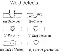
WELDING DEFECTS:
There are various types of welding defects which are given as follows:
AUTOMATION
Automation can be defined as the technology by which a process or procedure is performed without human assistance.
In other words, Automation or automatic control, is the use of various control systems for operating equipment such as machinery, processes in factories, boilers and heat treating ovens, switching on telephone networks, steering and stabilization of ships, aircraft and other applications and vehicles with minimal or reduced human intervention, with some processes have been completely automated.
Automation has been achieved by various means including mechanical, hydraulic, pneumatic, electrical, electronic devices and computers, usually in combination. Complicated systems, such as modem factories, airplanes and ships typically use all these combined techniques. The benefit of automation includes labor savings, savings in electricity costs, savings in material costs, and improvements to quality, accuracy and precision.
COMMONLY USED MACHINES AND TOOLS:
(i) Lathe machine:
\[\to \] Cylindrical turning: It involves the reduction of diameter of work-piece by removing material along the axis of work- piece from the cylindrical job's surface.
\[\to \] Taper turning: In this type, material is removed at an angle to the work-piece axis. And thus diameter of the work piece is increased or decreased.
\[\to \] Eccentric turning: In this type, the axis of work-piece does not coincide with the main axis.
\[\to \] Knurling: In this type, a diamond shaped impression is embossed on the work piece.
\[\to \] Facing: In this type, flat surface is developed by machining the ends of the work-piece.
\[\to \] Parting – off: In this type, the work piece is cut after obtaining required shape and size.
\[\to \] Chamfering: In this type, the end of the work – piece is bevelled.
(ii) Milling Machine:
\[\to \] Plain milling: In this type, a flat, horizontal surface is made paraller to the axis of rotation of plain milling cutter
\[\to \] Side milling: In this type, a flat vertical surface is developed on the side of work-piece with the help of a side milling cutter.
\[\to \] Face milling: In this type, face milling cutter is utilized with rotating motion about a perpendicular axis to the work piece.
\[\to \] End milling: In this type, a flat surface is developed.
The developed flat surface maybe horizontal, vertical or at an angle with the table.
\[\to \] Thread milling: In this type, threads are produced by utilizing a single or multiple thread milling cutter.
\[\to \] Form milling: In this type, irregular contours arc generated with the help of a form cutter.
(iii) Drilling machine:
\[\to \] Drilling: In this type, a cylindrical hole is developed with a drill which is a cutting tool having cutting edges
\[\to \] Boring: m this type, the hole (pre-existing is enlarged by using drilling operation.
\[\to \] Reaming: In this type, a preexisting hole produced by drilling or boring is finished and sized.
\[\to \] Counter-boring: In this type, the preexisting drilled hole is enlarged cylindrically at the end of the hole.
(iv) Shaper machine:
\[\to \] Horizontal surfaces: In this type, a flat surface is generated on a workpiece by holding it in a vise.
\[\to \] Vertical surfaces: In this type, the end of a workpiece. squaring up a component are produced.
\[\to \] Angular surfaces; In this type, an angular cut at as | angle other than 90° with the horizontal or vertical plane.
(v) Grinding machine:
\[\to \] Cylindrical surfaces: In this type, cylindrical surfaces of a work piece are finished by utilizing cylindrical grinders. \[\to \] Tapered surfaces: In this type, tapered surfaces of work piece are finished by using cylindrical grinders
\[\to \] Horizontal surfaces: In this type, the horizontal surfaces of work pieces are finished by utilizing the surface grinders.
\[\to \] Threaded surfaces: In this type, threads are produced by utilizing a thread grinding machine along with single -x m multiple rib wheels.


You need to login to perform this action.
You will be redirected in
3 sec

