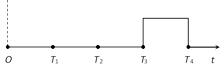
JEE Main & Advanced Physics Semiconducting Devices Question Bank Graphical Questions

  • question_answer
    The given figure shows the wave forms for two inputs A and B and that for the output Y of a logic circuit. The logic circuit is                                                                                            [UPSEAT 2002]   (Y)

    A)            An AND gate                           

    B)            An OR gate

    C)            A NAND gate                       

    D)            An NOT gate

    Correct Answer: A

    Solution :

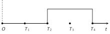
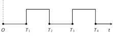
                       From the given waveforms, the following truth table can be made
    Time interval Inputs Output
    A B Y
    0 ® T1 0 0 0
    T1 ® T2 0 1 0
    T2 ® T3 1 0 0
    T3 ® T4 1 1 1
    This truth table is equivalent to ?AND? gate.


You need to login to perform this action.
You will be redirected in 3 sec spinner