| Draw a schematic diagram of a step up transformer. Explain the working principle. Deduce the expression for the secondary to primary voltage in terms of the number of turns in the two coils. In an ideal transformer, how is this ratio related to the currents in the two coils? How is the transformer used in large scale transmission and distribution of electrical energy over long distances. |
| Or |
| In an AC circuit containing a prime inductor, show that the voltage is ahead of current by \[\frac{\pi }{2}\] in phase. Draw the phasor diagram for the circuit and the graph of V and i versus \[\omega t.\] |
Answer:
Step up transformer is a device which changes an alternating voltage of smaller value to a greater value. This is done using the principle of mutual induction. 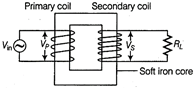 Transformer The transformer consists of two sets of coils insulated from each other are wound on a soft iron core. Let \[{{N}_{p}}\]= no. of turns in the primary coil and \[{{N}_{S}}\]= no. of turns in the secondary coil For a step up transformer, \[{{N}_{S}}>{{N}_{P}}.\] Principle of working When an alternating voltage is applied to the primary, the resulting current produces an alternating magnetic flux which links the secondary and induces an emf in it. The value of this emf depends on the number of turns in the secondary. Let \[\phi \] be the flux in each turn in the core due to the current flowing in the primary coil. The value of induced emf in the secondary is given by \[{{\varepsilon }_{s}}=-{{N}_{S}}\frac{d\phi }{dt}\] This alternating flux \[\phi \] also induces a back emf in the primary given by \[{{\varepsilon }_{P}}=-{{N}_{P}}\frac{d\phi }{dt}\] The voltage across the primary coil \[{{V}_{P}}={{\varepsilon }_{P}}=-{{N}_{P}}\frac{d\phi }{dt}\] ?(i) The voltage across the secondary coil when the switch is open is \[{{V}_{S}}={{\varepsilon }_{S}}=-{{N}_{P}}\frac{d\phi }{dt}\] ?(ii) From Eq. (i), \[\frac{d\phi }{dt}=\frac{{{V}_{P}}}{{{N}_{p}}}\] ?(iii) From Eq. (ii), \[\frac{d\phi }{dt}=\frac{{{V}_{S}}}{{{N}_{S}}}\] ?(iv) From Eqs. (iii) and (iv), \[\frac{{{V}_{S}}}{{{N}_{S}}}=\frac{{{V}_{P}}}{{{N}_{P}}}\] i.e., \[\frac{{{V}_{S}}}{{{V}_{P}}}=\frac{{{N}_{S}}}{{{N}_{P}}}\] For an ideal transformer, the resistance of primary and secondary coil are negligible, i.e., there are no energy losses Then input power = output power \[i{}_{p}{{V}_{P}}={{i}_{S}}{{V}_{S}}\] i.e., \[\frac{{{i}_{S}}}{{{i}_{P}}}=\frac{{{V}_{p}}}{{{V}_{S}}}=\frac{{{N}_{P}}}{{{N}_{S}}}\] The transformers are used in large scale transmission and distribution of electrical energy over long distances. The output voltages of the AC generators at power stations are stepped up using step-up transformers. This reduces the current and hence \[{{I}^{2}}R\] or resistive losses in the transmitting electric wires. At the area sub-stations near the consumers, this voltage is stepped down by step down transformers. Then at distributing sub-stations the voltage is again stepped down to 240 V and supplied to us. Or An AC circuit containing a pure inductor is shown below
 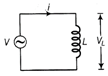 Let the voltage across the source be \[V={{V}_{m}}\sin \omega t\] Applying Kirchhoff's loop rule to the circuit, we get \[V-L\frac{di}{dt}=0,\] where L is the inductance and \[L\frac{di}{dt}\]is the self -induced emf in the inductor. \[\therefore \] \[V=L=\frac{di}{dt}\] i.e. \[\frac{di}{dt}=\frac{V}{L}=\frac{{{V}_{m}}\sin \omega t}{L}\] \[di=\frac{{{V}_{m}}}{L}\sin \omega t\,dt\] Integrating both sides we get, \[\int{di=\frac{{{V}_{m}}}{L}\int{\sin \omega t\,dt}}\] \[i=\frac{{{V}_{m}}}{L}\left( \frac{-\cos \,\,\omega t}{\omega } \right)+C\] \[i=\frac{-{{V}_{m}}}{\varepsilon L}\cos \omega t+C\] Here C is the integration constant which has the same dimensions of current and is constant. As the input voltage is alternating, the current is also alternating and time dependent. There is no constant value of current. Hence, C = 0 \[\therefore \] \[i=-\frac{{{V}_{m}}}{\omega L}\cos \omega t\] i.e., \[i=\frac{{{V}_{m}}}{\omega L}\sin \left( \omega t-\frac{\pi }{2} \right)\] \[\left[ \because \sin \left( \omega t-\frac{\pi }{2} \right)=-\cos \omega t \right]\] \[\therefore \] \[i={{l}_{m}}\sin \left( \frac{-\pi }{2} \right)\] \[\left[ where\,{{l}_{m}}=\frac{{{V}_{m}}}{\omega L} \right]\] By comparing the expression of V and /, we find that V is ahead of i by \[\frac{\pi }{2}\] in phase.
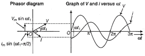


You need to login to perform this action.
You will be redirected in
3 sec

