| Directions : (1-5) |
| LCR Circuit |
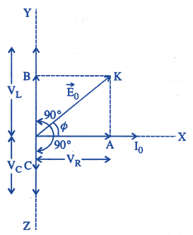
| When a pure resistance R, pure inductor L and an ideal capacitor of capacitance C is connected in series to a source of alternating e.m.f., then current at any instant through the three elements has the same amplitude and is respresented as \[I={{I}_{0}}\]\[\sin \omega t\] at. However, voltage across each element has a different phase relationship with the current as shown in graph. |
| The effective resistance of RLC circuit is called impedance (Z) of the circuit and the voltage leads the current by a phase angle \[\phi \]. |
 |
| A resistor of \[12\,\Omega \], a capacitor of reactance \[14\,\Omega \] and a pure inductor of inductance 0.1 H are joined in series and placed across 200 V, 50 Hz. a. c. supply. |
A) \[15\,\Omega \]
B) \[31\centerdot 4\,\Omega \]
C) \[20\,\Omega \]
D) \[30\,\Omega \]
Correct Answer: B
Solution :
Given : \[R=12\,\Omega \], \[{{X}_{C}}=14\Omega \], \[L=0\,.\,1\,H\] \[{{X}_{L}}=\omega L=2\pi vL=2\times 3\,.\,14\times 50\times 0\,.\,1=31\,.\,4\Omega \]


You need to login to perform this action.
You will be redirected in
3 sec

