| The output of the given circuit in Figure |
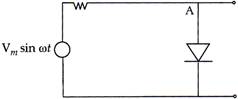 |
A) would be zero at all times.
B) would be like a half wave rectifier with positive cycles in output.
C) would be like a half wave rectifier with negative cycles in output.
D) would be like that of a full wave rectifier.
Correct Answer: C
Solution :
| Option [c] is correct. |
| Explanation: When positive cycle is at A, diode will be in forward bias and resistance due to diode is approximately zero so potential across diode will be about zero. |
| Similarly, when there is negative half cycle at A, diode will be in reverse bias and resistance will be maximum so potential difference across diode is \[{{V}_{m}}\] sin cot with negative at A, So we get only negative output at A, so it behaves like a half-wave rectifier with negative cycle at A in output, verifies the answer (C). |


You need to login to perform this action.
You will be redirected in
3 sec

