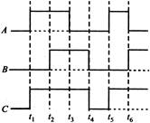
JEE Main & Advanced Physics Semiconducting Devices Question Bank Self Evaluation Test - Semiconductor Electronics: Materials, Devices and Simple Circuits

  • question_answer
    The figure shows a logic circuit with two inputs A and B and the output C. The voltage wave forms across A, B and C are as given. The logic gate circuit is:    

    A)  OR gate

    B)                     NOR gate

    C)  AND gate         

    D)         NAND gate

    Correct Answer: A

    Solution :

    [a]  


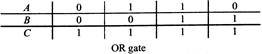
You need to login to perform this action.
You will be redirected in 3 sec spinner