
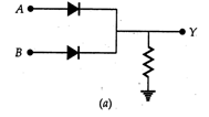

Answer:
(a) The circuit of Fig. (a) represents OR gate
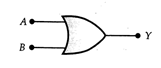 Logic symbol of OR gate.
Truth table of OR gate
(b) The circuit of Fig. (b) represents AND gate.
Input
A
Input
B
Output
\[\Upsilon \]
0
0
0
0
1
1
1
0
1
1
1
1
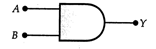 Logic symbol of AND gate.
Truth table of AND gate
Input
A
Input
B
Output
\[\Upsilon \]
0
0
0
0
1
0
1
0
0
1
1
1






You need to login to perform this action.
You will be redirected in
3 sec