| (i) Draw a labelled diagram of a moving coil galvanometer and explain its working. What is the function of radial magnetic field inside the coil? |
| (ii) How is moving coil galvanometer converted into a voltmeter? Explain, giving the necessary circuit diagram and the required mathematical relation used. |
| Or |
| (i) Find an expression for the force acting on a current carrying straight conductor kept in a uniform magnetic field. State the rule used to determine the direction of this force. |
| (ii) What is the magnitude of magnetic force per unit length on a wire carrying current of 8 A and making an angle \[30{}^\circ \] with the direction of uniform magnetic field of 0.5 T. |
Answer:
(iii) 0.6 N/m (i) Moving coil galvanometer Principle Its working is based on the fact that when a current carrying coil is placed in a magnetic field, it experiences a net torque. 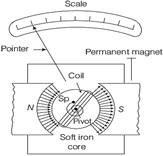
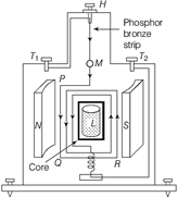 Working Suppose, the coil PQRS is suspended freely in the magnetic field. Let \[l=\] length PQ or RS of the coil, \[b=\] Breadth QR or SP of the coil And \[n=\]number of turns in the coil. Area of each turn of the coil, \[A=l\times b\] Let \[B=\] strength of the magnetic field in which coil is suspended. \[I=\] Current passing through the coil in the direction of PQRS. Let at any instant of time, \[\alpha \] be the angle which the normal drawn to the plane of the coil makes with the direction of magnetic field. The rectangular current carrying coil when placed in the magnetic field experiences a torque whose magnitude is given by \[\tau =nIBA\,\sin \,\alpha \] Due to this torque, the coil rotates and suspension wire get twisted. A restoring torque is set up in the suspension wire. Let \[\theta \] be the twist produced in the phosphor bronze strip due to rotation of the coil and K be the restoring torque per unit twist of the phosphor bronze strip. Then, total restoring torque produced \[=k\theta \] In equilibrium position of the coil, Deflecting torque = Restoring torque \[\therefore \] \[N\,I\,BA=k\theta \] Or \[I=\frac{k}{NBA}\theta =G\theta \] Where, \[\frac{k}{NBA}=G=a\] [Constant for a galvanometer] It is known as galvanometer constant. Current sensitivity of the galvanometer is the deflection produced per unit current. \[\frac{\phi }{I}=\frac{NAB}{k}\] Voltage sensitivity is the deflection produced per unit voltage. \[\therefore \] \[\frac{\phi }{V}=\frac{NAB}{k}\,\,\left( \frac{I}{V} \right)=\frac{NAB}{k}\frac{1}{R}\] [\[\therefore \,\,V=IR\]] The uniform radial magnetic field keeps the plane of the coil always parallel to the direction of the magnetic field. i.e. The angle between the plane of the coil and the magnetic field is zero for all the orientations of the coil. Thus, the normal to the plane of coil remains perpendicular to the magnetic field in all positions. (ii) A galvanometer can be converted into a voltmeter by connecting a very high resistance R in series with it. Let R is so chosen that current \[{{I}_{g}}\]gives full deflection in the galvanometer, where \[{{I}_{g}}\]is the range of galvanometer.
 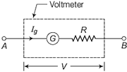 Let galvanometer of resistance G, range \[{{I}_{g}}\]is to be converted into voltmeter of range V (volt). Now, \[V={{I}_{g}}\,(G+R)\] \[\Rightarrow \] \[R+G=\frac{V}{{{I}_{g}}}\] \[\Rightarrow \] \[R=\frac{V}{{{I}_{g}}}-G\] The appropriate scale need to be graduated to measure potential difference. Or (i) Let a current carrying conductor (LM) of length \[l\]is placed in a uniform magnetic field directed along + Z-axis. Let current is flowing along +Y-axis.
 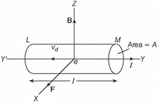 Let the drift speed of electrons be \[{{v}_{d}}\] along negative Y-axis. The magnitude of Lorentz force experienced by drifting electron, \[f=-\,e\,\,({{v}_{d}}\times B)\] ???. (i) Total number of free electrons in length \[l\] of conductor is \[N=n\,(Al)\] Where, \[n=\]number of free electrons per unit volume And A = area of cross-section of conductor. Therefore, total force on all drifting electrons of the conductor, \[F=Nf=(nAl)\,\,[-\,e\,\,({{v}_{d}}\times B)]\] \[\Rightarrow \] \[F=-n\,\,eAl\,\,[{{v}_{d}}\times B]\] \[\Rightarrow \] \[F=neA{{v}_{d}}\,\,lB\,\sin \,\theta \] Where, q is the angle between direction of flow of current and direction of magnetic field. \[F=(ne\,\,A{{v}_{d}})\,\,Bl\,\sin \,\theta \] \[\Rightarrow \] \[F=I\,\,Bl\sin \,\theta \] Where, \[I=ne\,\,A{{v}_{d}}\] This is the required expression for magnetic force on conductor. (ii) Fleming?s left hand rule: If the thumb, middle finger and forefinger of left hand are stretched mutually perpendicular to one another, such that forefinger points towards magnetic field, middle finger points towards the direction of flow of current, then the thumb gives the direction of force on the conductor. \[\therefore \] Magnetic force per unit length, \[f=\frac{F}{l}=Bl\,\sin \,\theta \] \[=0.15\times 8\times \sin \,30{}^\circ \] \[=0.6\,N\,/\,m\]


You need to login to perform this action.
You will be redirected in
3 sec

