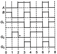
 Input-output waveforms (ii) The inputs, A and B, shown here, are used as the inputs for three different gates, \[{{G}_{1}},\,{{G}_{2}}\] and \[{{G}_{3}}.\] One by one. The outputs, obtained in the three cases, have the forms shown. Identify the three gates and write their symbols.
 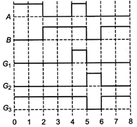 Input-output waveforms Or
 | (i) The same input signal is applied to both the (input) terminals of a given logic gate. If the output is the |
| (a) same as the (common) input signal. |
| (b) inverted with respect to the (common) input signal. |
| Identify the logic gates involved and write their truth tables in each case. Also draw output wave forms corresponding to inputs of each gate. |
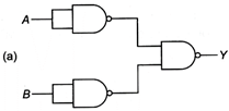
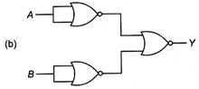
| (ii) Write the truth tables for each of the combinations shown below. Also, identify the logic operations performed by them. |
 Logic gates
Answer:
(i) Gate \[{{G}_{1}}\] is a NAND gate 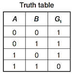 Gate \[{{G}_{2}}\] is an NOR gate.
 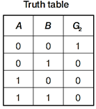 Gate \[{{G}_{3}}\] is a AND gate.
 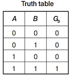 (ii) Gate \[{{G}_{1}}\] is AND gate. Symbol
 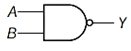 Gate \[{{G}_{2}}\] is NOR gate. Symbol
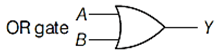
 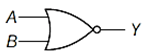 Gate \[{{G}_{3}}\] is OR gate. Symbol
 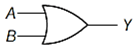 Or (i) (a) If same input is given to both input terminals and the output is same as the input, it can be an AND or OR gate.
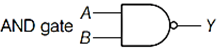
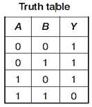
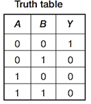
 (b) If same input is given to the input terminals and output is inverted with respect to input, then it can be a NAND gate or NOR gate.
 ![]()
 (ii) (a) Truth table for this combination is
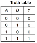
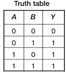
 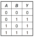 This is an OR gate. Logic operation is \[Y=A+B\] (b) Truth table for this combination is
 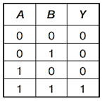 This is an AND gate. Logic operation is \[Y=A\cdot B\]


You need to login to perform this action.
You will be redirected in
3 sec

