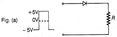
| In the following circuits shown, if the input waveform is as shown in figure what will be the output waveform |
| (i) across R in Fig. (a) |
| (ii) across the diode in Fig. (b) |
| Assume that the diode is ideal. |
 Output waveform across R
 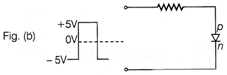 Output waveform across the diode
Answer:
The input waveform is of digital nature, which means, it is either \[-5V\,or+5V.\] (i) When the input is \[-5V,\] the diode gets reverse biased and so, no output is obtained across R, i.e. \[{{V}_{out}}=0\]  Output waveform across R When the input becomes \[+5V,\] the diode gets forward biased and a current flows through resistor ft. As diode is ideal, there is no potential difference across the diode and the output across R will be exactly 5 V Thus, the output will be either 0 or \[+5V.\] The waveform is shown in Fig. (a). (ii) When input is \[-\,5V,\] the diode gets reverse biased and so, there is no current in-the circuit and no output is obtained across R; the potential of terminal \[\rho \] will be \[-\,5V\] lower than that of n, so the potential difference across diode across diode will be \[-\,5V\] When input is 0 to 5V the diode is forward biased having zero potential difference across the terminals.
  Output waveform across diode


You need to login to perform this action.
You will be redirected in
3 sec

