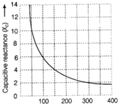
| Figure shown below, shows how the reactance of a capacitor varies with frequency. |
 \[Frequency\,\,(Hz)\to \]
Graph capacitive reactance versus frequency
\[Frequency\,\,(Hz)\to \]
Graph capacitive reactance versus frequency
|
| (i) Use the information of the graph to calculate the value of capacitance of capacitor. |
| (ii) An inductor of inductance L has the same reactance as the capacitor at 100 Hz. Find the value of L. |
| (iii) Using the same axes, draw a graph of reactance against the frequency for the inductor given in part (ii). |
| (iv) If this capacitor and inductor were connected in series to a resistor of \[10\,\Omega ,\] what would be the impedance of the combination at 300 Hz? |
| (v) A charged \[30\,\mu F\]capacitor is connected to a 27 mH inductor. What is the angular frequency of free oscillations of the circuit? |
| Or |
| Draw a labelled diagram of AC generator, explain its theory and working. An armature coil consists of 20 turns of wire, each of area \[A=0.09\text{ }{{m}^{2}}\] and total |
| resistance \[15\,\Omega .\] It rotates in a magnetic field of 0.5T at a constant frequency \[150/\pi \,Hz.\] Calculate the value of maximum emf produced in the coil. |
Answer:
(i) From graph, at frequency, f = 100 Hz, reactance \[{{X}_{C}}=6\,\Omega \] \[\therefore \] Capacitive reactance \[({{X}_{C}})=1/2\pi fC\] \[\Rightarrow \] \[C=\frac{1}{2\pi f{{X}_{C}}}=\frac{1}{2\times 3.14\times 100\times 6}\] Capacitance of capacitor, \[C=2.65\times {{10}^{-4}}F\] (ii) According to the problem, at f =100 Hz, \[{{X}_{L}}={{X}_{C}}=6\,\Omega \] But inductive reactance, \[{{X}_{L}}=2\pi fL\Rightarrow L=\frac{{{X}_{L}}}{2\pi f}=\frac{6}{2\times 3.14\times 100}\] Inductance of inductor, \[L=9.55\times {{10}^{-3}}H\] \[{{X}_{L}}=2\pi fL\Rightarrow {{X}_{L}}\propto f\] (iii) The required graph is as follows: 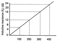 \[Frequency\,\,(Hz)\to \] Graph inductive reactance versus frequency (iv) According to the problem, at f = 300 Hz For \[{{X}_{C}}\propto \frac{1}{f}\Rightarrow X{{'}_{C}}=\frac{{{X}_{C}}}{3}=\frac{6}{3}=2\,\Omega \] Similarly, \[{{X}_{L}}'=3{{X}_{L}}=3\times 6=18\,\Omega \] Also, resistance, \[R=10\,\Omega \] \[\therefore \] Impedance, \[Z=\sqrt{{{R}^{2}}+{{({{X}_{L}}-{{X}_{C}})}^{2}}}\] \[=\sqrt{{{(10)}^{2}}+{{(18-2)}^{2}}}=\sqrt{356}=18.87\,\Omega \] (v) For the oscillations, the angular frequency should be resonant frequency. Resonant angular frequency of oscillation of the circuit, \[{{\omega }_{r}}=\frac{1}{\sqrt{LC}}=\frac{1}{\sqrt{27\times {{10}^{-3}}\times 30\times {{10}^{-6}}}}\] \[=\frac{{{10}^{4}}}{9}=1.1\times {{10}^{3}}rad\,\,{{s}^{-1}}\] Or An AC generator is a device which converts mechanical energy into electrical energy Principle When the magnetic flux linked with a coil changes an induced emf and hence an induced current is set-up in it.
 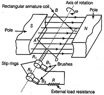 AC generator Theory and working Let initially the plane of armature coil be perpendicular to the direction of magnetic field. It rotates with uniform angular speed to. After time t, the area vector of coil make an angle \[\theta \] with the magnetic field. \[\therefore \] \[\omega =\frac{\theta }{t}\Rightarrow \theta =\omega t\] \[\therefore \] Magnetic flux linked with coil at that instant \[\phi =NBA\cos \theta \] where, N = Number of turns of coil or \[\phi =NBA\cos \omega t\] [from Eq. (i)] ?(ii) \[\therefore \] \[\frac{d\phi }{dt}=-NBA\,\omega \sin \omega t\] \[\Rightarrow \] \[\frac{-d\phi }{dt}=NBA\,\omega \,\sin \omega t\] By Faraday's law, \[\therefore \] Induced emf, \[e=NBA\,\omega \sin \omega t\]\[\left[ \because \,e=\frac{-d\phi }{dt} \right]\] or \[e=(NBA\,\omega )\sin \omega t\] \[e={{e}_{0}}\sin \omega t\] where, eg is maximum induced emf \[=NBA\,\omega \] The variation of emf with time
 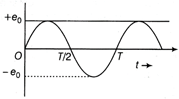 Graph between emf and time During the first half-cycle, coil rotates in such a way that AB moves upward and CD downward. By Fleming's right hand rule, the induced current flows from A to B and C to D. The current flow through brush \[{{B}_{1}}\] acting as positive terminal and brush \[{{B}_{2}}\] as negative terminal. During the next half cycle, when CD moves upward and AB downward induced current flows in opposite direction and brush \[{{B}_{2}}\] act as positive terminal and brush 6, as negative. Thus, the direction of current gets reversed after every half cycle. Hence, alternating current is produced in AC generated/dynamo. Here, number of turns, N = 20, area, \[A=0.09\,{{m}^{2}}\] and magnetic field, B = 0.5T. Frequency, \[f=\frac{150}{\pi }Hz\] The maximum emf or peak emf is given by \[{{e}_{0}}=NBA\omega ,\] where \[\omega =2\pi f\] \[\therefore \] \[{{e}_{0}}=NBA\,(2\pi f)\] \[\Rightarrow \] \[{{e}_{0}}=20\times 0.5\times 0.09\times \left( 2\pi \times \frac{150}{\pi } \right)\] = 270 V


You need to login to perform this action.
You will be redirected in
3 sec

