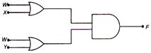
 The output F of the circuit is represented by:
A) W + (X + V)
B) W + (X Y)
C) W. (X . Y)
D) W. (X + Y)
Correct Answer: B
Solution :
The circuit consists of 2 OR gates and 1 AND gate. Output of upper OR gate is W + X. Output of lower OR gate is W + V.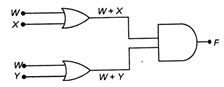 Net output is \[F=(W+X).(W+Y)\] \[=W.W+WY+XW+XY\] \[=W+WY+XW+XY\] \[=W(1+Y)+XW+XY\] \[=W+WX+XY\] \[=W(1+X)+XY\] \[F=W+XY\]


You need to login to perform this action.
You will be redirected in
3 sec

