A) 0.4 \[\mu F\]
B) 3 \[\mu F\]
C) 4 \[\mu F\]
D) 2 \[\mu F\]
Correct Answer: A
Solution :
The circuit diagram is shown in figure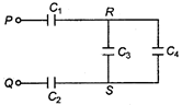 As shown, \[{{C}_{3}}\] and \[{{C}_{4}}\] are in parallel, hence their effective capacitance is \[C={{C}_{3}}+{{C}_{4}}=1+1=2\mu F\] Now \[{{C}_{1}},{{C}_{2}}\] and C are in series, hence their effective capacitance is \[\frac{1}{C}=\frac{1}{{{C}_{1}}}+\frac{1}{C}+\frac{1}{{{C}_{2}}}\] \[=\frac{1}{1}+\frac{1}{2}+\frac{1}{1}\] \[=2+\frac{1}{2}=\frac{2}{5}\]
  \[\therefore \] \[C=\frac{2}{5}=0.4\,\mu F\]


You need to login to perform this action.
You will be redirected in
3 sec

