Engineering Drawing
Category : Railways
Engineering Drawing
ENGINEERING DRAWING
Engineering drawing is a type of technical drawing, created within the technical drawing discipline, and is used to define the requirements for engineered items. It is also a graphical language that communicates ideas and information from one mind to another.
The purpose of engineering drawing is to capture all the geometric features of a product or a component accurately and unambiguously.
Its end goal is to convey the information that will allow a manufacturer to produce that component.
ENGINEERING DRAWINGS: COMMON FEATURES
Geometry – shape of the object; represented as views and how the object will look when viewed from various standard directions
, such as front, top, side, etc.
Dimensions – size of the object captured in accepted units.
Tolerances – allowable variations for every dimension.
Material – represents what the item is made of.
Finish – specifies the surface quality of item, functional or cosmetic.
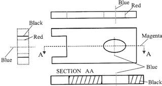
Example of an Engineering Drawing
Here is an example of an engineering drawing (an isometric view of the same object is show bellow). The different line types are colored for clarity.
Magenta = phantom line or cutting plane line
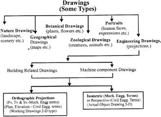
TYPES OF DRAWING
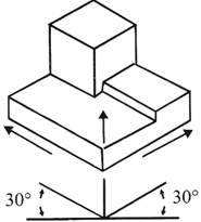
Isometric Drawing
Representation of the object in figure below is called an isometric drawing. This is one of a family of three-dimensional views called pictorial drawings. In an isometric drawing, the object's vertical lines are drawn vertically, and the horizontal lines in the width and depth planes are shown at 30 degrees to the horizontal. When drawn under these guidelines, the lines parallel to these three axes are at their true (scale) lengths. Lines that are not parallel to these axes will not be of their true length.
Figure An Isometric Drawing
A engineering drawing should show everything: beaa complete understanding of the object should be possible from the drawing-
If the isometric drawing can show all details and all dimensions on one drawing, it is ideal. One can pack a great deal of information into an isometric drawing. However, if the object in figure above had a hole on the back side, it would not be visible using a single isometric drawing. In order to get a more complete view of the object, an orthographic projection may be used.
Orthographic Drawing
Imagine that we have an object suspended by transparent threads inside a glass box, as in figure below.
Figure - The block suspended in a glass box
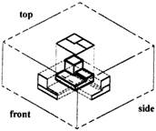
Then draw the object on each of three faces as seen from that direction. Unfold the box (figure below) and you have the three views. We call this an "orthographic" or "multi-view" drawing.
Figure - The creation of an orthographic or multi-view drawing
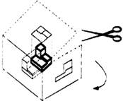
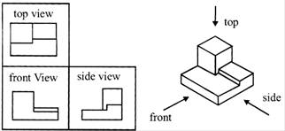
Figure below shows how the three views appear on a piece of paper after unfolding the box.
Figure - A multi-view drawing and its explanation
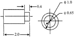
The views that reveal every detail about the object. Three views are not always necessary; we need only as many views as are required to describe the object fully. For example, some objects need only two views, while others need four. The circular object in figure below requires only two views.
Figure -An object needing only two orthogonal views
Dimensioning
Figure -An isometric view with dimensions
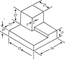
We have "dimensioned" the object in the isometric drawing in figure above. As a general guideline to dimensioning, try to think that we would make an object and dimension it in the most useful way. Put in exactly as many dimensions as are necessary for the crafts-person to make it -no more, no less. Do not put in redundant dimensions. Not only will these clutter the drawing, but if "tolerances" or accuracy levels have been included, the redundant dimensions often lead to conflicts when the tolerance allowances can be added in different ways.
Repeatedly measuring from one point to another will lead to inaccuracies. It is often better to measure from one end to various points. That gives the dimensions a reference standard. It is helpful to choose the placement of the dimension in the order in which a machinist would create the part. So that convention may take some experience.
VIEWS OF ENGINEERING DRAWING:
Views
In engineering drawing there are six principle views of an object, front, top, L side, R side, rear, and back views. The three most commonly views drawn on a technical drawing are the front, back and side views most other views are not needed. Other views may be needed in order for the person who is creating the Part, to better visualize it in order to properly manufacture it.
In most cases, a single view is not sufficient to show all necessary features, and several views are used such as:
Auxiliary views:
An auxiliary view is an orthographic view that is projected into any plane other than one of the six primary views. These views are typically used when an object contains some sort of inclined plane. Using the auxiliary view allows for that inclined plane (and any other significant features) to be projected in their true size and shape. The true size and shape of any feature in an engineering drawing can only be known when the Line of Sight (LOS) is perpendicular to the plane being referenced. It is shown like a three-dimensional object. Auxiliary views tend to make use of axonometric projection. When existing all by themselves, auxiliary views are sometimes known as pictorials.
Section Views
Projected views (either Auxiliary or Multi-view) which show a cross section of the source object along the specified cut plane.
These views are commonly used to show internal features with more clarity than may be available using regular projections or hidden lines. In assembly drawings, hardware components (e.g. nuts, screws, washers) are typically not sectioned.
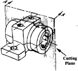
Cross-Sectional Views
A cross-sectional view portrays a cut-away portion of the object and is another way to show hidden components in a device. Imagine a plane that cuts vertically through the center of the pillow block as shown in figure below.
Figure - Pillow Block
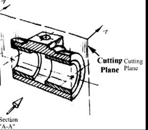
Then imagine removing the material from the front of this plane, as shown in figure below:
Figure - Pillow Block
PROJECTIONS OF ENGINEERING DRAWING:
The projection is achieved by the use of imaginary "projectors". Graphical projection is a protocol, used in technical drawing, by which an image of a three-dimensional object is projected onto a planar surface without the aid of numerical calculation. By this protocol the technician may produce the envisioned picture on a planar surface such as drawing paper. The protocols provide a uniform imaging procedure among people trained in technical graphics (mechanical drawing, computer aided design, etc.).
Types of projections:
Orthographic Projection:
Orthographic projection is a way of representing a 3-dimensional object in two dimensions. It is a form of parallel projection; here the view direction is orthogonal to the projection plane, resulting in each plane of the scene appearing in affine transformation on viewing surface. It is further divided into Multi-view Orthographic projections and axonometric projection. A multi-view projection is a type of orthographic projection that shows the object as it looks from the front, right, left, top, bottom, or back (e. g. the primary views), and is typically positioned relative to each other according to the rules of either first-angle or third- angle projection.
First-angle projection
Third-angle Projection
Auxiliary Projections
The auxiliary view is an orthographic view that is projected into any plane other than one of the 6 principal views. The views are used when an object contains some sort of the inclined plane.
Using the auxiliary view allows for inclined plane to be projected in true size and shape. The true size and shape of any feature in a technical drawing can only be known when the Line of Sight is perpendicular to the plane which is considered as reference.
Isometric projection
An isometric projection shows the object from angles in which the scales along each axis of the object are equal. Isometric projection corresponds to rotation of the object by \[\pm \,\,45{}^\circ \]about the vertical axis, followed by rotation of approximately \[\pm \,\,35.264{}^\circ \]\[\left[ =arc-sin\,\,\left( tan\,\,\left( 30{}^\circ \right) \right) \right]\]about the horizontal axis starting from an orthographic projection view. "Isometric" comes from the Greek for "same measure". One of the things that make isometric drawings so attractive is the ease with which\[60{}^\circ \]angles can be constructed with only a compass and straightedge. Isometric projection is a type of axonometric projection. The other two types of axonometric projection are:
Oblique projection:
An oblique projection is a simple type of graphical projection used for producing pictorial, two-dimensional images of three-dimensional objects:
In both oblique projection and orthographic projection, parallel lines of the source object produce parallel lines in the projected image.
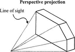
Perspective projection:
Perspective is an approximate representation on a flat surface, of an image as it is perceived by the eye. The two most characteristic features of perspective are that objects are drawn:
DRAWING INSTRUMENTS
Drawing instruments are used to draw straight lines, circles, and curves accurately concisely.
The drawing tools are like drawing board, mini drafter, instrument box containing compass, divider, Set squares, protractor, French curves, drawing sheet, pencils, and erasers.
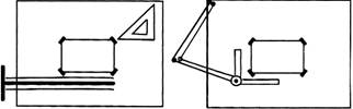
Drawing Tools
To prepare a drawing, one can use manual drafting instruments (figure below) or computer-aided drafting or design, or CAD. The basic drawing standards and conventions are the same regardless of what design tool we use to make the drawings. In learning drafting, we will approach it from the perspective of manual drafting. If the drawing is made without either instruments or
CAD, it is called a freehand sketch.
Figure ? Drawing Tools
LINE
Line is the most basic design 'tool' on which almost every piece of art relies. A line has length, width, tone, and texture. It may divide space, define a form, describe contour, or suggest direction.
Types of lines
There are mainly four types of lines are present in engineering drawing:
Which are used in the representation of the diagrams are of mainly 4 types they are
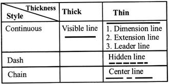
Classification of Lines
Lines can also be classified by a letter classification in which each line is given a letter.
Scale
Plans are usually "scale drawings", meaning that the plans are drawn at specific ratio relative to the actual size of the place or object. Various scales may be used for different drawings in a set.
For example, a floor plan may be drawn at \[1:50\,\,(1:48\,\,or\,\,{{V}_{4}}''=1'0'')\] whereas a detailed view may be drawn at \[1:25\,\,(1:24\,\,or\,\,{{V}_{2}}''=1'0'')\]
Site plans are often drawn at \[1:200\,\,or\,\,1:100\]
Drawing Standards
Drawing standards are set of rules that govern how the technical drawings are represented. These are used so that everyone can commonly understand the meaning of drawn picture.
Drawing Sheet
We have many types and sizes of drawing sheets such as: A4, A3, A2, A1, A0 etc.
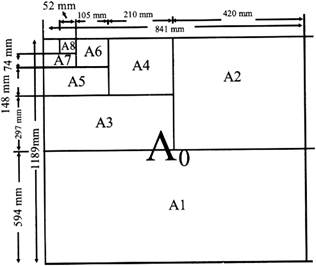
Standard sheet size (JIS)
A4 \[210\times 297\]
A3 \[297\times 420\]
A2 \[420\times 594\]
A1 \[594\times 841\]
A0 \[841\times 1189\]
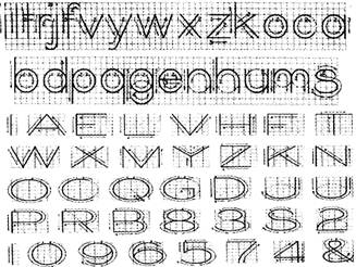
TECHNICAL LETTERING
Technical lettering is the process of forming letters, numerals, and other characters in technical drawing. It is used to describe, or provide detailed specifications for, an object. With the goals of legibility and uniformity, styles are standardized and lettering ability has little relationship to normal writing ability Engineering-drawings use a Gothic sans-serif script, formed by a series of short strokes. Lower case letters are rare in most drawings of machines.
Lettering and numbering should be in a perfect manner.
For example in figure below the upper and lower case letters are neatly drawn.
GEOMETRIC FIGURE
Geometric shapes are found everywhere. Take a moment to analyze products or objects we use every day. Geometric shapes and solids are the basis of these products. Engineers who have a strong understanding of these shapes, solids, and other geometric relationships can help designers develop and create solutions to a variety of problems. As designers progress through the design process and these design solutions are formalized, the level of accuracy and precision in the design specifications must increase. Conceptual sketches are converted to computer models and formal drawings, which include annotations describing the size and characteristics of the design features. A strong understanding of shapes and other geometric relationships is necessary to effectively and efficiently develop these computer and graphic representations.
Types of geometric shape:
There are many types of geometric shapes:
Square
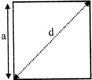
The area of a square can be calculated as \[A={{a}^{2}}\]
The side of a square can be calculated as \[a={{A}^{1/2}}\]
The diagonal of a square can be calculated as\[d=a\sqrt{2}\]
Rectangle
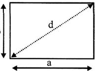
The area of a rectangle can be calculated as A=ab
The diagonal of a rectangle can be calculated as
\[d={{({{a}^{2}}+{{b}^{2}})}^{1/2}}\]
Parallelogram
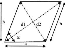
The area of a parallelogram can be calculated as \[A=a\,\,h=a\,\,b\,\sin \,\,\alpha \]
The diameters of a parallelogram can be calculated as
\[{{d}_{1}}={{({{(a+h\,\,cot\,\,\alpha )}^{2}}+{{h}^{2}})}^{1/2}}\]
\[{{d}_{2}}={{({{(a-h\,\,cot\,\,\alpha )}^{2}}+{{h}^{2}})}^{1/2}}\]
Equilateral Triangle
An equilateral triangle is a triangle in which all three sides are equal.
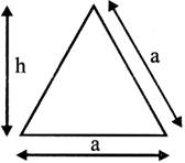
The area of an equilateral triangle can be calculated as \[A=({{a}^{2}}/3){{3}^{1/2}}\]
The area of an equilateral triangle can be calculated as \[h=a/2\,\,{{3}^{1/2}}\]
Triangle
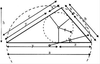
The area of a triangle can be calculated as
\[A=a\,\,h/2=r\,\,s\]
\[r=a\,\,h/2s\]
\[R=b\,\,c/2\,\,h\]
\[s=(a+b+c)/2\]
\[x=s-a\]
\[y=s-b\]
\[z=s-c\]
Trapezoid
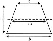
The area of a trapezoid can be calculated as
\[A=1/2(a+b)h=m\,\,h\,\,m=(a+b)/2\]
Hexagon
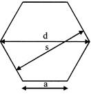
The area of a hexagon can be calculated as
\[A=3/2\,\,{{a}^{2}}\,\,{{3}^{1/2}}\]
\[d=2\,\,a\]
\[=\frac{2}{\sqrt{3s}}=1.1547005\,\,s\]
\[s=\sqrt{3}/2d=0.866025\,\,d\]
Circle
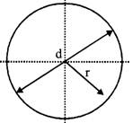
The area of a circle can be calculated as
\[A=\pi /4\,\,{{d}^{2}}=\pi {{r}^{2}}=0.785..{{d}^{2}}\]
\[C=2\pi r=\pi \,\,d\]
where
C = circumference
Sector of Circle
Area of a sector of circle can be expressed as
\[A=1/2{{\theta }_{r}}{{r}^{2}}\]
\[=1/360\,\,{{\theta }_{d}}\pi {{r}^{2}}\]
where
\[{{\theta }_{r}}\]= angle in radians
\[{{\theta }_{d}}\]= angle in degrees
Segment of Circle
Area of a segment of circle can be expressed as
\[A=1/2\,\,({{\theta }_{r}}-\sin {{\theta }_{r}})\,\,{{r}^{2}}\]
\[=1/2\,\,(\pi {{\theta }_{d}}/180-sin{{\theta }_{d}})\,\,{{r}^{2}}\]
Right Circular Cylinder
Lateral surface area of a right circular circle can be expressed as
\[A=2\,\pi \,r\,h\]
where
h = height of cylinder (m, ft)
r = radius of base (m, ft)
Right Circular Cone
Lateral surface area of a right circular cone can be expressed as
\[A=\pi \,r\,l\]
\[=\pi r\,\,{{({{r}^{2}}+{{h}^{2}})}^{1/2}}\]
where
h = height of cone (m, ft)
r = radius of base (m, ft)
/= slant length (m, ft)
Sphere
Lateral surface area of a sphere can be expressed as
\[A=4\,\pi \,{{r}^{2}}\]
Where
r = radius of base (m, ft)
SYMBOLIC REPRESENTATION:
Drawing Symbols provide a convenient way to draw geometrical shapes. To draw a geometrical shape, such as a pentagon or hexagon, select an appropriate symbol from the menu, specify the size of the symbol, and it is drawn at the indicated point.
Example:
Arrows (or pointers) in a drawing are commonly used to specify a direction for any reason. There are several arrow styles available in CADD programs. We can choose from simple two-point arrows to arrows passing through a number of points, and from simple to fency arrow styles. To draw an arrow, we need to indicate the points through which the arrow will pass.


You need to login to perform this action.
You will be redirected in
3 sec

