Electrical Measurement and Instrumentation
Category : Railways
Electrical Measurement and Instrumentation
The measurement methods can be analog or digital methods, deflection or null methods, active or passive methods, direct or indirect methods and absolute or secondary methods. Measurement generally involves an instruments as a physical means of determining an unknown quantity or a variable called the parameter.
The instrument is a means for determining the value or magnitude of the measured. The instruments can also be divided into separate classes according to several criteria as, analog or digital instrument, deflection or null type instruments, power operated (active) or self generating (passive) instruments, contacting or non contacting instruments, mechanical or electrical instruments and or control instruments.
CLASSIFICATION OF INSTRUMENTS
Permanent Magnet Moving Coil Instrument
Deflecting torque, \[{{T}_{d}}\propto I\]
And controlling torque, \[{{T}_{c}}={{K}_{c}}\theta \]
At steady position of pointer, \[{{T}_{c}}={{T}_{d}}\]
And thus, \[I\propto \theta \]
- since the deflection is directly proportional to the current flowing through the instrument, we get a uniform scale for the instrument.
- D.C. voltage and D.C. current can be measured using
PMMC instruments.
Moving Iron Type Instrument
In movingiron instruments the movable system consists of one or more pieces of specially-shaped soft iron, which are so pivoted as to be acted upon by the magnetic field produced by the current in coil. There are two general types of moving-iron instruments namely.
(i) Attraction type (ii) Repulsion type.
Attraction Type
Deflecting torque, \[{{T}_{d}}=K{{I}^{2}}\]
And controlling torque, \[{{T}_{c}}={{K}_{1}}\sin \theta \]
At steady position of pointer, \[{{T}_{c}}={{T}_{d}}\]
And thus, \[\theta \propto {{I}^{2}}\]
Repulsion Type
In repulsion type instrument, two vanes of soft iron are used inside the coil. One vane is fixed and the other one is free to move. When current flows through the coil, both vanes are magnetized and therefore, there is a force of repulsion between the two and this force acts as the driving force for the instrument. Two different designs of repulsion type moving iron type instruments are common - radial type and co-axial type.
Electro Dynamometer Type Instrument
Induction Type Instruments
MEASUREMENT OF VOLTAGE
Voltmeter is an instrument used for measuring the voltage between any two points in an electrical circuit. There are two types of voltmeters: Analog and Digital. In an analog voltmeter, a pointer shows deflection across the scale, which indicates the voltage reading with respect to the applied current; whereas a digital voltmeter gives a numerical display of the voltage according to the applied current, with the help of an ADC (analog- to-digital converter).
Analog Voltmeter: The fig. shows the D'arsonval type moving coil galvanometer. The device consists of a pointer, a fall deflection scale, magnets and a coil. The pointer is attached with the coil, which is suspended in a magnetic field, as shown in the figure. Under no biasing condition, the pointer is at the zero position, i.e. at the center of the scale, which also helps to notify if the voltage changes its polarity. Now, in order to measure the voltage, the galvanometer is connected in circuit with a series resistor as shown in figure below; the resistor is connected in series to ensure that the angular rotations of the indicator are directly proportional to the applied voltage. Normally, this device is used in case of direct current; however, we can also have an AC source by using a rectifier in the circuit. The output of this voltmeter is expressed in 'ohms per volt'.
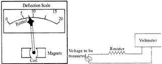
Fig.; Analog Voltmeter Fig.: Voltmeter connection in circuit
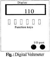
Digital Voltmeter: A Digital voltmeter uses the analog-to-digital converter for displaying the voltage on the numerical display.
The accuracy of a Digital voltmeter is higher than that of an analog voltmeter. The main parts of Digital voltmeter are an amplifier and a numeric display as shown in figure below. Just like the analog voltmeter, a digital voltmeter is also connected in series with the circuit, but the value of series resistance is fixed by the manufacturer (generally about 10 mega ohms).
MEASUREMENT OF CURRENT
Current is measured with the help of an instrument known as 'Ammeter'. It consists of a deflection scale and a pointer. An ammeter is always connected in parallel with the circuit as shown in fig., and the simplest method for determining circuit current is:
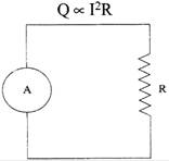
Fig.: Circuit arrangement for Current measurement using ammeter
MEASUREMENT OF POWER
Power is generally measured through Wattmeters of which there are two types - electrodynamometer type and the induction type.
Electrodynamometer Type Wattmeter
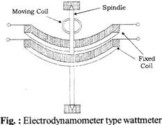
Electrodynamometer type wattmeter consists of two coif as shown in the figure below.
Fixed coil is split up into two identical coils and are made up of thick copper wires. This fixed coils are connected in series with the load and so they carry the current in the circuit, thus, they form the current coil of the circuit.
Moving coil is mounted on the spindle and is placed in between the two fixed coil. The moving coil is connected across the voltage and therefore it forms the pressure coil of the wattmeter.
Spring control method is used for producing controlling torque and damping torque is produced by air friction damping system,
The moving coil act as a current carrying conductor placed in a magnetic field and thus force induced in it and since pointer is connected to this moving coil, it deflects on the scale.
This deflection is controlled by the controlling spring and at last pointer comes to rest showing a reading.
Induction Type Wattmeter

Fig.: Induction type wattmeter
MEASUREMENT OF ENERGY
Energy is measured by an induction type energy meter, the arrangement for which is shown in the figure below and its whole operation is divided into four parts such as:
(a) Driving System
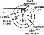
Fig.: Induction type energymeter
(b) Moving system
(c) Braking system
(d) Registering system
INSTRUMENT TRANSFORMER
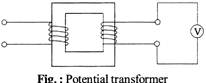
The transformer used in conjunction with measuring instruments for measurement purposes is called an Instrument Transformer. To measure current. Current Transformers (CTs) are used and to measure voltage (or potential), Potential Transformers (PTs) are used.
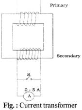
Current Transformer
Potential Transformer
BRIDGES
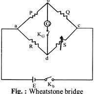
Wheatstone Bridge
This bridge is used to measure the medium resistance and its arrangement is shown in fig.
Let P and Q = known resistances known as ratio arms
S = known variable resistance
R = unknown resistance
\[{{K}_{b}}\]and\[{{K}_{g}}\]Battery and Galvanometer key
E = supply voltage
The value of the unknown resistance when the bridge is in
P balanced state is \[R=\frac{P}{Q}S\]
Kelvin's Double Bridge
Kelvin's double bridge is used to measure low resistance and its arrangement is shown in the fig.
p and q = first set of ratio arms
P and Q = second set of ratio arms
S = known variable resistance
R = unknown resistance
r= lead resistance
E and \[{{K}_{g}}\]= Battery and Galvanometer key
Also. \[\frac{p}{q}=\frac{P}{Q}\]
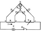
Fig.: Kelvin's bridge
The value of unknown resistance when the bridge is in a balanced state is
\[R=\frac{P}{Q}S\]
Maxwell's Induction Bridge
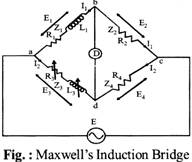
This bridge is used to measure self inductance is shown in fig.
\[{{R}_{1}}\]= resistance of the coil (unknown)
\[{{L}_{1}}\]= inductance of the coil (unknown)
\[{{R}_{2}}\]= known non-inductive resistances
\[{{R}_{3}}\]= variable resistance
\[{{L}_{3}}\]= known inductance
\[{{r}_{3}}\]= internal resistance of \[{{L}_{3}}\]
At balanced condition,
\[{{R}_{1}}=\frac{{{R}_{2}}}{{{R}_{4}}}({{R}_{3}}+{{r}_{3}}),\,\,\,{{L}_{1}}={{L}_{3}}\frac{{{R}_{2}}}{{{R}_{4}}}\]
\[Q-factor=\frac{\omega {{L}_{3}}}{{{R}_{3}}+{{r}_{3}}}\]
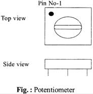
POTENTIOMETER
A potentiometer is a three terminal device shown in fig. which is used as a variable resistor. The outer terminals are fixed, while the middle terminal can vary; the middle terminal is either in if screw-shape or in the form of a control shaft along with a wiper, The screw moves over the resistive element and shows continuous variation in the resistance of the element, which is connected between the outside and the middle terminal of if potentiometer. A potentiometer is basically used to control the voltage of the circuit. Although there is one more application of the potentiometer: it can be used as a rheostat by connecting its middle terminal with an outside terminal. (A rheostat is mainly used to control the circuit current.)
MULTIMETER
A Multimeter is a measuring instrument which is used to measure several functions like current, voltage and resistance. Multimeters are of two types: analog and digital. In an analog multimeter, a micro ammeter is used which consists of a pointer and a deflection scale whereas in digital Multimeter, the measured value is displayed in numerals on a digital screen, the display can either be in the seven segment format or in the liquid style display of an LCD. Nowadays, digital multimeters are preferred over analog all types of measurements. But analog multimeters are still when we have to monitor the values which rapidly vary it a wide range. applications of multimeter:
(a) Measuring of AC and DC
(b) Measuring voltage and current
(c) Measuring resistance
(d) Testing of continuity in circuit
Q–METER
Q–meter is a device which is used to determine the quality factor of a circuit. Generally, this device is used in radio frequency circuits, where it is desirable to know how much amount of energy dissipated from the system in a non-ideal reactive form. Q- factor is given as-
\[Q=2\pi \times \frac{Peak\,\,Energy\,\,Stored}{Energy\,\,dissipated\,\,per\,Cycle}\]
ERROR ANALYSIS
There are three basic types of errors which are obtained while taking measurements in lab with any electrical system and these are —
(1) Random Error
(2) Systematic Error
(3) Gross Error
(1) Random Error: Those uncontrolled or uncertain fluctuations which randomly affect the results of experiments are called random errors. Examples include the change in temperature due to sunlight around temperature sensors, air fluctuations caused by opening and closing of doors, etc. This error type is difficult to remove but can be solved by calculating the estimated standard deviation of collected data.
(2) Systematic Error: Instrumental mistakes, methodological and personal mistakes fall under this category. Instrumental errors can be caused in many ways, for e.g. an improper placement of device. Methodological errors are caused because of the selection of wrong alternatives for experiment, and personal mistakes are caused by observers and performers like noting down incorrect readings, etc.
These errors can be easily eliminated by careful observation and correct operation of instruments.
(3) Gross Error: This error is caused either by an instrument failure or the carelessness of the experimenter. In order to minimize this error, a set of precision measurements must be taken by the experimenter.


You need to login to perform this action.
You will be redirected in
3 sec

