Category : JEE Main & Advanced
Rectifier is a circuit which converts ac to unidirectional pulsating output. In other words it converts ac to dc. It is of following two types
(1) Half wave rectifier : When the P-N junction diode rectifies half of the ac wave, it is called half wave rectifier
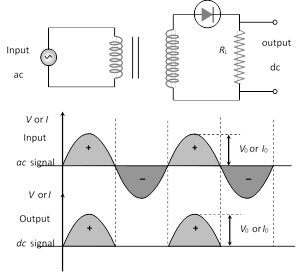
(i) During positive half cycle
Diode \[\xrightarrow{{}}\] forward biased
Output signal \[\xrightarrow{{}}\] obtained
(ii) During negative half cycle
Diode \[\xrightarrow{{}}\] reverse biased
Output signal \[\xrightarrow{{}}\] not obtained
(iii) Output voltage is obtained across the load resistance \[{{R}_{L}}\]. It is not constant but pulsating (mixture of ac and dc) in nature .
(iv) Average output in one cycle
\[{{I}_{dc}}=\frac{{{I}_{0}}}{\pi }\] and \[{{V}_{dc}}=\frac{{{V}_{0}}}{\pi };\,\,{{I}_{0}}=\frac{{{V}_{0}}}{{{r}_{f}}+{{R}_{L}}}\]
(\[{{r}_{f}}=\]forward biased resistance)
(v) r.m.s. output : \[{{I}_{rms}}=\frac{{{I}_{0}}}{2},\,{{V}_{rms}}=\frac{{{V}_{0}}}{2}\]
(vi) The ratio of the effective alternating component of the output voltage or current to the dc component is known as ripple factor.
\[r=\frac{{{I}_{ac}}}{{{I}_{dc}}}={{\left[ {{\left( \frac{{{I}_{rms}}}{{{I}_{dc}}} \right)}^{2}}-1 \right]}^{1/2}}=1.21\]
(vii) Peak inverse voltage (PIV) : The maximum reverse biased voltage that can be applied before commoncement of Zener region is called the PIV. When diode is not conducting PIV across it \[={{V}_{0}}\]
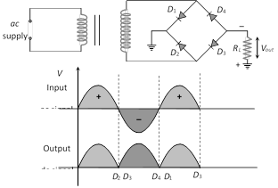
(viii) Efficiency :
If \[{{R}_{L}}>>{{r}_{f}}\] then \[\eta =40.6%\]
If \[{{R}_{L}}={{r}_{f}}\] then \[\eta =20.3%\]
(ix) Form factor = \[\frac{{{I}_{rms}}}{{{I}_{dc}}}=\frac{\pi }{2}=1.57\]
(x) The ripple frequency \[(\omega )\] for half wave rectifier is same as that of ac.
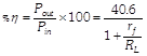
(2) Full wave rectifier : It rectifies both halves of ac input signal.
(i) During positive half cycle
Diode : \[{{D}_{1}}\] \[\xrightarrow{\,\,\,\,\,\,\,}\] forward biased
\[{{D}_{2}}\] \[\xrightarrow{\,\,\,\,\,\,\,}\] reverse biased
Output signal \[\xrightarrow{\,\,\,\,\,\,\,}\]obtained due to \[{{D}_{1}}\] only
(ii) During negative half cycle
Diode : \[{{D}_{1}}\] \[\xrightarrow{\,\,\,\,\,\,\,}\] reverse biased
\[{{D}_{2}}\] \[\xrightarrow{\,\,\,\,\,\,\,}\] forward biased
Output signal \[\xrightarrow{\,\,\,\,\,\,\,}\] obtained due to \[{{D}_{2}}\] only
(iii) Fluctuating dc ![]() constant dc.
constant dc.
(iv) Output voltage is obtained across the load resistance RL. It is not constant but pulsating in nature.
(v) Average output : \[{{V}_{av}}=\frac{2{{V}_{0}}}{\pi },\,{{I}_{av}}=\frac{2{{I}_{0}}}{\pi }\]
(vi) r.m.s. output : \[{{V}_{rms}}=\frac{{{V}_{0}}}{\sqrt{2}},\,{{I}_{rms}}=\frac{{{I}_{0}}}{\sqrt{2}}\]
(vii) Ripple factor : \[r=0.48=48%\]
(viii) Ripple frequency : The ripple frequency of full wave rectifier = 2 \[\times \] (Frequency of input ac)
(ix) Peak inverse voltage (PIV) : It's value is \[2{{V}_{0}}\]
(x) Efficiency : 
for \[{{r}_{ff}}<<{{R}_{L}},\,\,\eta =81.2%\]
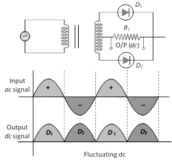
(3) Full wave bridge rectifier : Four diodes \[{{D}_{1}},\,\,{{D}_{2,\,\,}}{{D}_{3}}\] and \[{{D}_{4}}\] are used in the circuit.
During positive half cycle \[{{D}_{1}}\] and \[{{D}_{3}}\] are forward biased and D2 and D4 are reverse biased
During negative half cycle \[{{D}_{2}}\] and \[{{D}_{4}}\] are forward biased and \[{{D}_{1}}\] and \[{{D}_{3}}\] are reverse biased


You need to login to perform this action.
You will be redirected in
3 sec

