
 Light
Light is the important part of our life. Some objects produce light and are called luminous object, while some do not produce light and therefore are called non luminous object. The big source of light is the Sun. The other sources of light are, burning candles, torches, electric bulbs, etc. Light travels through vacuum and also through some mediums, for example, through air, glass and other transparent objects. The best example of traveling of light through vacuum is traveling of sun light from the Sun to the Earth.
The objects that allow the passing of light through them are called transparent object, i.e. glass, water, air, etc. The objects that allow passing only of some portion of light through them, are called translucent objects.
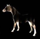
Look at the following picture of translucent object
Light
Light is the important part of our life. Some objects produce light and are called luminous object, while some do not produce light and therefore are called non luminous object. The big source of light is the Sun. The other sources of light are, burning candles, torches, electric bulbs, etc. Light travels through vacuum and also through some mediums, for example, through air, glass and other transparent objects. The best example of traveling of light through vacuum is traveling of sun light from the Sun to the Earth.
The objects that allow the passing of light through them are called transparent object, i.e. glass, water, air, etc. The objects that allow passing only of some portion of light through them, are called translucent objects.
Look at the following picture of translucent object
 Opaque objects do not allow passing of light through them. A piece of wood does not allow passing of light through it, therefore is called opaque object. The shadow of an object is formed due to the interruption of light. The light from light producing body is radiated towards different direction and a shadow of an object, which interrupt light, is formed at the opposite direction from where light is coming. For example, if the light is coming from east direction, the shadow of the object, which interrupt the light, forms in west direction. Shadow is not possible of a the transparent object. Because it allows the passing of light through
Look at the following picture of shadow formation
Opaque objects do not allow passing of light through them. A piece of wood does not allow passing of light through it, therefore is called opaque object. The shadow of an object is formed due to the interruption of light. The light from light producing body is radiated towards different direction and a shadow of an object, which interrupt light, is formed at the opposite direction from where light is coming. For example, if the light is coming from east direction, the shadow of the object, which interrupt the light, forms in west direction. Shadow is not possible of a the transparent object. Because it allows the passing of light through
Look at the following picture of shadow formation
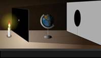 In the above picture, light from the candle is passing through the hole on the globe and shadow is formed on the opposite side of the light producing body.There are two parts of a shadow, umbra and penumbra. Umbra is the part of shadow, which is in complete darkness and does not receive light from the source. Penumbra is the part of shadow, which receives some part of light from the source.
Look at the following picture of path of the light
In the above picture, light from the candle is passing through the hole on the globe and shadow is formed on the opposite side of the light producing body.There are two parts of a shadow, umbra and penumbra. Umbra is the part of shadow, which is in complete darkness and does not receive light from the source. Penumbra is the part of shadow, which receives some part of light from the source.
Look at the following picture of path of the light
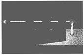 In the picture above, light from candle is passing through the hole of the three cardboards. A thin streak of light is appeared at the far end of the cardboard. This proves that the light travels in straight line. This property of light is called rectilinear propagation of light.
Look at the following picture of the solar eclipse
In the picture above, light from candle is passing through the hole of the three cardboards. A thin streak of light is appeared at the far end of the cardboard. This proves that the light travels in straight line. This property of light is called rectilinear propagation of light.
Look at the following picture of the solar eclipse
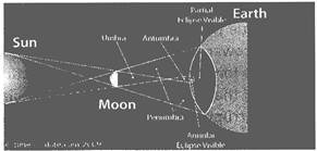 Solar eclipse is the formation of shadow of Moon on the surface of the Earth.
The solar eclipse is possible due to the passing of Moon between the Earth and the Sun. Light from the Sun is reflected by the surface of the Moon and shadow is formed on the surface of the Earth.
Look at the following picture more...
Solar eclipse is the formation of shadow of Moon on the surface of the Earth.
The solar eclipse is possible due to the passing of Moon between the Earth and the Sun. Light from the Sun is reflected by the surface of the Moon and shadow is formed on the surface of the Earth.
Look at the following picture more...  Formation of Image by Plane Mirror
The picture of our face in the mirror is called image and our face is called object. The formation of our image in the mirror is possible due to the reflection of light. In the absence of light, the formation of image is not possible. If we put a mirror in front of our face in the dark (light is not available) we cannot see the image of the face. Light is therefore an important factor for the formation of image.
Images formed are of two types:
Formation of Image by Plane Mirror
The picture of our face in the mirror is called image and our face is called object. The formation of our image in the mirror is possible due to the reflection of light. In the absence of light, the formation of image is not possible. If we put a mirror in front of our face in the dark (light is not available) we cannot see the image of the face. Light is therefore an important factor for the formation of image.
Images formed are of two types:
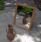
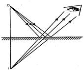 Fig. (1) Plane mirror Fig. (2) Image formation in a plane mirror
In the figure (1), a virtual image is formed by a plane mirror. In the figure (2), formation of a virtual image by a plane mirror is shown. An object (0) is placed in front of the mirror. Incident ray falls from 0 and get reflected by the mirror. The reflected rays are produced backward and they meet at the point /. The observer receives the reflected rays and image as shown at /. The image of the object is not the actual intersection of light and therefore is called virtual image. The incident ray falls on the plane mirror by 90° retraces its path or reflected through the same path. An incident ray falling on the plane mirror by 6 is reflected by the same angle (9).
Fig. (1) Plane mirror Fig. (2) Image formation in a plane mirror
In the figure (1), a virtual image is formed by a plane mirror. In the figure (2), formation of a virtual image by a plane mirror is shown. An object (0) is placed in front of the mirror. Incident ray falls from 0 and get reflected by the mirror. The reflected rays are produced backward and they meet at the point /. The observer receives the reflected rays and image as shown at /. The image of the object is not the actual intersection of light and therefore is called virtual image. The incident ray falls on the plane mirror by 90° retraces its path or reflected through the same path. An incident ray falling on the plane mirror by 6 is reflected by the same angle (9).

 The image is formed by a plane mirror is due to the reflection of light. Why an image is called virtual when it is formed by a plane mirror?
(a) It can be obtained on the screen
(b) It cannot be obtained on the screen
(c) Real image is formed
(d) All of these
(e) None of these
Answer: (b)
The image is formed by a plane mirror is due to the reflection of light. Why an image is called virtual when it is formed by a plane mirror?
(a) It can be obtained on the screen
(b) It cannot be obtained on the screen
(c) Real image is formed
(d) All of these
(e) None of these
Answer: (b)
 The image, which is formed by a plane mirror is due to the reflection of light. At which one of the following point images of an object is formed?
(a) Imaginary meeting point of reflected rays
(b) Imaginary meeting point of incidence rays
(c) At the meeting point of both the rays
(d) All of these
(e) None of these
Answer: more...
The image, which is formed by a plane mirror is due to the reflection of light. At which one of the following point images of an object is formed?
(a) Imaginary meeting point of reflected rays
(b) Imaginary meeting point of incidence rays
(c) At the meeting point of both the rays
(d) All of these
(e) None of these
Answer: more...  Spherical Mirrors
The name of the spherical mirror itself indicates that it is the part of the sphere. There are two types of spherical mirrors, convex and concave mirror. The reflective side of the concave mirror bulges away from the observer and in the convex mirror it bulges towards the observer.
For the better understanding of the concave and convex mirror, a tablespoon may be taken as an example. The inner surface of the table spoon is the shape of concave and the outer surface is the shape of convex.
Look at the following pictures of convex mirror
Spherical Mirrors
The name of the spherical mirror itself indicates that it is the part of the sphere. There are two types of spherical mirrors, convex and concave mirror. The reflective side of the concave mirror bulges away from the observer and in the convex mirror it bulges towards the observer.
For the better understanding of the concave and convex mirror, a tablespoon may be taken as an example. The inner surface of the table spoon is the shape of concave and the outer surface is the shape of convex.
Look at the following pictures of convex mirror
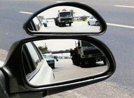
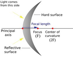 Fig.(1) Virtual image (In convex mirror) Fig.(2) Index of a convex mirror
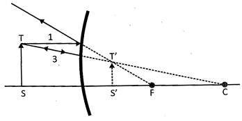 Fig. (3) Image formed by convex mirror
In the picture (1), a virtual image is shown by a convex mirror. Convex mirror is used in automobiles to get the wider view of the automobile. The curved surface of convex mirror gives the wider and clear view of the object approaching. It is used in departmental stores to get the wider view of the inside of store. Convex mirror reflects light outwards. It cannot be focused on an object, therefore cannot be used to focus light. The center of curvature and focus, both are imaginary. Therefore, they form virtual image. The center of the shiny image of the convex mirror is called vertex and denoted by V. When parallel light rays strike on the convex mirror, it gets reflected. Virtual image is formed at the imaginary intersecting point of the reflected rays, as shown in the figure (3).
Look at the following pictures of concave mirror
Fig. (3) Image formed by convex mirror
In the picture (1), a virtual image is shown by a convex mirror. Convex mirror is used in automobiles to get the wider view of the automobile. The curved surface of convex mirror gives the wider and clear view of the object approaching. It is used in departmental stores to get the wider view of the inside of store. Convex mirror reflects light outwards. It cannot be focused on an object, therefore cannot be used to focus light. The center of curvature and focus, both are imaginary. Therefore, they form virtual image. The center of the shiny image of the convex mirror is called vertex and denoted by V. When parallel light rays strike on the convex mirror, it gets reflected. Virtual image is formed at the imaginary intersecting point of the reflected rays, as shown in the figure (3).
Look at the following pictures of concave mirror
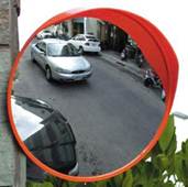
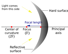 Fig. (1) Real image Fig (2) Index of a concave mirror
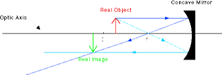 Fig (3) Image by a concave mirror
In the figure (1), an image is shown formed by a concave mirror. A real image is formed by the concave mirror when object is placed in front of the mirror. A concave mirror reflects light and reflected rays of light intersects each other outside the mirror, therefore real image (not virtual) is formed.
The center of curvature is the center of sphere and denoted by C, radius of the curvature is denoted by r. The center of the shiny surface of the mirror is called the pole of the mirror and it is denoted by P. In the figure (3), incident rays are reflected and meet at a point called focus .which is denoted by F. Focus, centerof curvature and pole of the mirror more...
Fig (3) Image by a concave mirror
In the figure (1), an image is shown formed by a concave mirror. A real image is formed by the concave mirror when object is placed in front of the mirror. A concave mirror reflects light and reflected rays of light intersects each other outside the mirror, therefore real image (not virtual) is formed.
The center of curvature is the center of sphere and denoted by C, radius of the curvature is denoted by r. The center of the shiny surface of the mirror is called the pole of the mirror and it is denoted by P. In the figure (3), incident rays are reflected and meet at a point called focus .which is denoted by F. Focus, centerof curvature and pole of the mirror more...  Lenses and Formation of Image
There are two types of lens:
Lenses and Formation of Image
There are two types of lens:
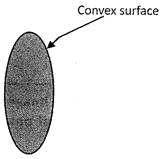
 Fig. (1) Side view of convex lens Fig. (1) Front view of convex lens
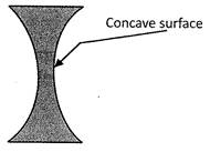
 Fig. (3) Side view of concave lens Fig. (3) Front view of concave lens
Lenses are made up of spherical mirrors. The same thickness of the both curvature causes zero optical power. Two surface of mirror combined and forms a lens. The surfaces of the lens are ideally perpendicular to each other. The surface of the lens can be of plane, or of spherical mirrors. The joining line between the vertexes of the both surface of the lens is called its axis.
Fig. (3) Side view of concave lens Fig. (3) Front view of concave lens
Lenses are made up of spherical mirrors. The same thickness of the both curvature causes zero optical power. Two surface of mirror combined and forms a lens. The surfaces of the lens are ideally perpendicular to each other. The surface of the lens can be of plane, or of spherical mirrors. The joining line between the vertexes of the both surface of the lens is called its axis.
 Convex Lens
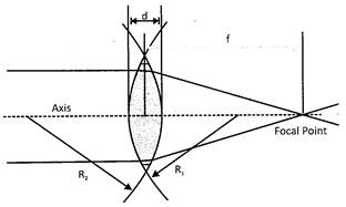
In the figure below/is the focal length, a is the distance between the two surfaces of the lens. R is the radius of curvature of the first surface of the lens and R^ is the radius of curvature of the secondary lens.
Look at the following picture of image formation by a convex lens
Convex Lens
In the figure below/is the focal length, a is the distance between the two surfaces of the lens. R is the radius of curvature of the first surface of the lens and R^ is the radius of curvature of the secondary lens.
Look at the following picture of image formation by a convex lens
 Formation of Image by a Convex Lens
When the position of the object before a convex lens is changed, nature of the image formed by the lens is also changed. Formation of image by a convex lens when object is at the different position in front of the lens and characteristics of the image has been given below.
Formation of Image by a Convex Lens
When the position of the object before a convex lens is changed, nature of the image formed by the lens is also changed. Formation of image by a convex lens when object is at the different position in front of the lens and characteristics of the image has been given below.
| Position of object | more...
 Water
Water is a chemical substance with the chemical formula H2O. A molecule of water contains one oxygen and two hydrogen atoms connected by covalent bonds. Water exists in nature in all the three states. Water exists as vapour in air, as liquid in rivers, sea and under the ground and as solid in the polar regions and as snow on the mountains. Water covers about three-fourth of the earth's surface. Only 2.5% of the water available on the earth is fresh water and suitable for drinking, rest is in the form of oceans as salty water. Water
Water is a chemical substance with the chemical formula H2O. A molecule of water contains one oxygen and two hydrogen atoms connected by covalent bonds. Water exists in nature in all the three states. Water exists as vapour in air, as liquid in rivers, sea and under the ground and as solid in the polar regions and as snow on the mountains. Water covers about three-fourth of the earth's surface. Only 2.5% of the water available on the earth is fresh water and suitable for drinking, rest is in the form of oceans as salty water.  Water Sources
The various sources of water are:
Surface water: Water is available on the earth's surface in the form of oceans, rivers, lakes, etc.
Note: About 70.9% of earth's surface is covered by water.
Ground water: The rain water gets collected deep inside the layers of the earth as groundwater. Traditionally, wells were used for utilizing the ground water. Now a days groundwater is pumped with the help of power operated tube wells.
Rainwater: Rainfall is the primary source of water. It replenishes the surface water and groundwater.. Water Sources
The various sources of water are:
Surface water: Water is available on the earth's surface in the form of oceans, rivers, lakes, etc.
Note: About 70.9% of earth's surface is covered by water.
Ground water: The rain water gets collected deep inside the layers of the earth as groundwater. Traditionally, wells were used for utilizing the ground water. Now a days groundwater is pumped with the help of power operated tube wells.
Rainwater: Rainfall is the primary source of water. It replenishes the surface water and groundwater..  Scarcity of Water
The reasons for the scarcity of water are:
Pattern of Rainfall: The rainfall occurs mainly in rainy season. Therefore, there is scarcity of water in the other seasons.
Loss of Water: All the rain water that falls on the ground cannot be utilized and is lost due to evaporation and runs off the land into streams.
Overuse: Overuse of water is another reason for its scarcity.
Pollution: Pollution of water bodies is one of the main causes of scarcity of water.
Deforestation: Deforestation of hill slopes and other areas leads to excessive runoff of water. In addition to this, negligence and non-proper maintenance of old water tanks, ponds and wells leads to water shortage Scarcity of Water
The reasons for the scarcity of water are:
Pattern of Rainfall: The rainfall occurs mainly in rainy season. Therefore, there is scarcity of water in the other seasons.
Loss of Water: All the rain water that falls on the ground cannot be utilized and is lost due to evaporation and runs off the land into streams.
Overuse: Overuse of water is another reason for its scarcity.
Pollution: Pollution of water bodies is one of the main causes of scarcity of water.
Deforestation: Deforestation of hill slopes and other areas leads to excessive runoff of water. In addition to this, negligence and non-proper maintenance of old water tanks, ponds and wells leads to water shortage

 What is the chemical formula of water?
(a) What is the chemical formula of water?
(a)  (b)
(b)  (c)
(c)  (d)
(d)  (e) None of these
Answer: (b)
(e) None of these
Answer: (b)
 In which one of the following states water is present on earth?
(a) Solid
(b) Liquid
(c) Gas
(d) All of these
(e) None of these
Answer: (d) In which one of the following states water is present on earth?
(a) Solid
(b) Liquid
(c) Gas
(d) All of these
(e) None of these
Answer: (d)
 Water is a chemical substance with the chemical formula.
A water molecule consists of one oxygen and two hydrogen atoms.
Only 2.5% of the water available on the earth is fresh water.
Approximately 70% of the fresh water used by human beings is for agriculture.
Water is a chemical substance with the chemical formula.
A water molecule consists of one oxygen and two hydrogen atoms.
Only 2.5% of the water available on the earth is fresh water.
Approximately 70% of the fresh water used by human beings is for agriculture.  Time
Time is used to measure the duration in which things occur, and interval between two occurrences. Time give us the idea of the duration of the occurrence of a certain event. For example, repetition of the day, night and seasons, phases of the Moon, appearance of certain star in the sky etc.
In ancient time, people observed stars and constellations for such estimations. Appearance of the certain star in the sky was the indicator of new season. But this way of estimation was very inconvenient as stars and constellations appear only at night and could not be seen at cloudy nights. Therefore, they started to develop new systems to measure the day and night durations.
Sand Clock Time
Time is used to measure the duration in which things occur, and interval between two occurrences. Time give us the idea of the duration of the occurrence of a certain event. For example, repetition of the day, night and seasons, phases of the Moon, appearance of certain star in the sky etc.
In ancient time, people observed stars and constellations for such estimations. Appearance of the certain star in the sky was the indicator of new season. But this way of estimation was very inconvenient as stars and constellations appear only at night and could not be seen at cloudy nights. Therefore, they started to develop new systems to measure the day and night durations.
Sand Clock
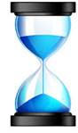 Sand clock is one of the instruments, which was used earlier to measure the time duration. Sand clock consists of two glass bulbs placed one above the other and are connected with the help of a narrow glass tube. Sand flows from the top to the bottom. When the top bulb gets empty, clock is inverted so that lower glass tube comes up and sand clock keeps on working. The sand takes a fixed duration of time to flow from one glass tube to other. In this way, earlier people used to measure time duration of an event.
In the modern time we use clocks to know the duration of time. Clock uses second as a unit; 60 second is equal to 1 minute and 60 minute to one hour.
Modern basis of measuring time duration
60 seconds = 1 minute
60 minutes = 1 hour
24 hours = 1 day
365 days = 1 year
10 years = 1 decade
10 decades = 1 century
10 century’s = 1 millennium
Sand clock is one of the instruments, which was used earlier to measure the time duration. Sand clock consists of two glass bulbs placed one above the other and are connected with the help of a narrow glass tube. Sand flows from the top to the bottom. When the top bulb gets empty, clock is inverted so that lower glass tube comes up and sand clock keeps on working. The sand takes a fixed duration of time to flow from one glass tube to other. In this way, earlier people used to measure time duration of an event.
In the modern time we use clocks to know the duration of time. Clock uses second as a unit; 60 second is equal to 1 minute and 60 minute to one hour.
Modern basis of measuring time duration
60 seconds = 1 minute
60 minutes = 1 hour
24 hours = 1 day
365 days = 1 year
10 years = 1 decade
10 decades = 1 century
10 century’s = 1 millennium
 Velocity
 is a physical quantity that is used to show the direction in which object is moving, as well as speed of the object. Thus velocity gives more close information about the position of the object. Velocity is a vector quantity as it has both direction and magnitude. Velocity
Velocity is a physical quantity that is used to show the direction in which object is moving, as well as speed of the object. Thus velocity gives more close information about the position of the object. Velocity is a vector quantity as it has both direction and magnitude.
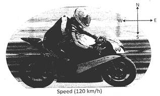
 Uniform Velocity
When an object moves on a straight path with a constant speed and does not change direction, the object is said to be in the uniform velocity. When an object moves on a circular path, it might have uniform speed but not uniform velocity, as an object has to change its direction continuously to move on a circular path. Uniform Velocity
When an object moves on a straight path with a constant speed and does not change direction, the object is said to be in the uniform velocity. When an object moves on a circular path, it might have uniform speed but not uniform velocity, as an object has to change its direction continuously to move on a circular path.
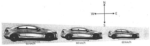 In the above figure, the car is moving in east direction with a constant speed. Therefore, it is said that the car is moving with uniform velocity.
Non-uniform velocity
If more...
In the above figure, the car is moving in east direction with a constant speed. Therefore, it is said that the car is moving with uniform velocity.
Non-uniform velocity
If more...  Distance and Displacement
Distance and displacement are two different physical quantities. Let us study them in detail Distance and Displacement
Distance and displacement are two different physical quantities. Let us study them in detail
 Distance
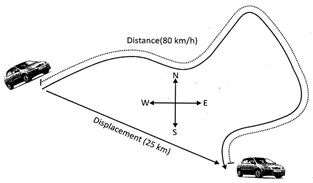
When an object moves from one place to other, it covers some distance. Distance is the total length of the path on which the object move. Distance does not shows the direction. It just represents the length, which an object has traveled. Therefore, distance is a scalar quantity. Distance
When an object moves from one place to other, it covers some distance. Distance is the total length of the path on which the object move. Distance does not shows the direction. It just represents the length, which an object has traveled. Therefore, distance is a scalar quantity.
 Displacement is the distance between initial point from where object started to move and the final point where the object stopped. Displacement shows finally the object in which direction and at how far from the initial place sifted. Therefore displacement shows direction as well as distance. And it is a vector quantity.
  Speed
When a body moves, it covers some distance. How much distance does it cover in a given time or how long will it take to cover a particular distance? Such questions arise in our day to day life. To solve such queries a term "speed" is used. Speed is related to time and distance. With the help of speed we can find the distance or the required time to cover the particular distance. The standard unit of the time is second. The distance covered by an object in a unit time is called speed. Speed is a scalar quantity as it does not tell about the direction.
\[\text{Speed}\,\,\text{=}\,\,\frac{\text{Distance}}{\text{Time}}\] Speed
When a body moves, it covers some distance. How much distance does it cover in a given time or how long will it take to cover a particular distance? Such questions arise in our day to day life. To solve such queries a term "speed" is used. Speed is related to time and distance. With the help of speed we can find the distance or the required time to cover the particular distance. The standard unit of the time is second. The distance covered by an object in a unit time is called speed. Speed is a scalar quantity as it does not tell about the direction.
\[\text{Speed}\,\,\text{=}\,\,\frac{\text{Distance}}{\text{Time}}\]
 Uniform Speed
If an object does not change its speed while moving, the object is said to be in uniform speed. Uniform Speed
If an object does not change its speed while moving, the object is said to be in uniform speed.
 Look at the following figure
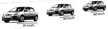 Speed of the car does not vary in different interval of time. Therefore speed of the car is uniform.
Graphical representation of uniform speed.
Speed of the car does not vary in different interval of time. Therefore speed of the car is uniform.
Graphical representation of uniform speed.
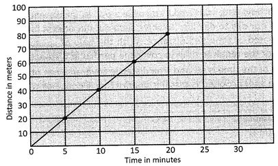 Time distance graph of a body, which has uniform, speed, is a straight line
Non-uniform Speed
If an object changes its speed while moving, the object is said to be in non uniform, speed.
Time distance graph of a body, which has uniform, speed, is a straight line
Non-uniform Speed
If an object changes its speed while moving, the object is said to be in non uniform, speed.
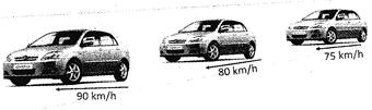 In the above figure, speed of the car varies at different interval of time. Therefore, speed of the car is non-uniform.
Graphical representation of non-uniform speed.
In the above figure, speed of the car varies at different interval of time. Therefore, speed of the car is non-uniform.
Graphical representation of non-uniform speed.
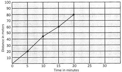 Distance-time graph of a body, which has non-uniform speed, is a curved line.

 Which one of the following is true for the uniform speed
(a) If speed of the object varies at different interval of time, the object has uniform speed
(b) If speed of the object is constant at different intervals of time, the object has uniform speed
(c) If a moving object suddenly comes to rest, the object has uniform speed
(d) All of these
(e) None of these
Answer: (b) Which one of the following is true for the uniform speed
(a) If speed of the object varies at different interval of time, the object has uniform speed
(b) If speed of the object is constant at different intervals of time, the object has uniform speed
(c) If a moving object suddenly comes to rest, the object has uniform speed
(d) All of these
(e) None of these
Answer: (b)
 A cyclist covers 25 km in first hour, 30 km in the second hour and 35 km in the third hour. The cyclist is in _____.
(a) Uniform motion
(b) Non uniform motion
(c) Cannot be find that the body is in uniform motion or in non uniform motion
(d) All of these
(e) None of these
Answer: (b) A cyclist covers 25 km in first hour, 30 km in the second hour and 35 km in the third hour. The cyclist is in _____.
(a) Uniform motion
(b) Non uniform motion
(c) Cannot be find that the body is in uniform motion or in non uniform motion
(d) All of these
(e) None of these
Answer: (b) Current Affairs CategoriesArchive
Trending Current Affairs



You need to login to perform this action. |