 Energy bands are of following types
(1) Valence band : The energy band formed by a series of energy levels containing valence electrons is known as valence band. At 0 K, the electrons fills the energy levels in valence band starting from lowest one.
(i) This band is always filled with electrons.
(ii) This is the band of maximum energy.
(iii) Electrons are not capable of gaining energy from external electric field.
(iv) No flow of current due to electrons present in this band.
(v) The highest energy level which can be occupied by an electron in valence band at 0 K is called fermi level.
(2) Conduction band : The higher energy level band is called the conduction band.
(i) It is also called empty band of minimum energy.
(ii) This band is partially filled by the electrons.
(iii) In this band the electrons can gain energy from external electric field.
(iv) The electrons in the conduction band are called the free electrons. They are able to move any where within the volume of the solid.
(v) Current flows due to such electrons.
(3) Forbidden energy gap \[(\Delta {{E}_{g}})\] : Energy gap between conduction band and valence band \[\Delta {{E}_{g}}={{(C.B.)}_{\min }}-{{(V.B.)}_{\max }}\]
Energy bands are of following types
(1) Valence band : The energy band formed by a series of energy levels containing valence electrons is known as valence band. At 0 K, the electrons fills the energy levels in valence band starting from lowest one.
(i) This band is always filled with electrons.
(ii) This is the band of maximum energy.
(iii) Electrons are not capable of gaining energy from external electric field.
(iv) No flow of current due to electrons present in this band.
(v) The highest energy level which can be occupied by an electron in valence band at 0 K is called fermi level.
(2) Conduction band : The higher energy level band is called the conduction band.
(i) It is also called empty band of minimum energy.
(ii) This band is partially filled by the electrons.
(iii) In this band the electrons can gain energy from external electric field.
(iv) The electrons in the conduction band are called the free electrons. They are able to move any where within the volume of the solid.
(v) Current flows due to such electrons.
(3) Forbidden energy gap \[(\Delta {{E}_{g}})\] : Energy gap between conduction band and valence band \[\Delta {{E}_{g}}={{(C.B.)}_{\min }}-{{(V.B.)}_{\max }}\]
 (i) No free electron is present in forbidden energy gap.
(ii) Width of forbidden energy gap depends upon the nature of substance.
(iii) As temperature increases \[(\uparrow )\], forbidden energy gap decreases \[(\downarrow )\] very slightly.
Types of solid
(i) No free electron is present in forbidden energy gap.
(ii) Width of forbidden energy gap depends upon the nature of substance.
(iii) As temperature increases \[(\uparrow )\], forbidden energy gap decreases \[(\downarrow )\] very slightly.
Types of solid
| Properties | Conductors | Insulators | Semiconductors | |||||||||||
| Electrical conductivity | \[{{10}^{2}}\] to 108 ?/m | \[{{10}^{8}}\,\mho /m\] | \[{{10}^{-5}}\] to \[{{10}^{0}}\,\mho /m\] | |||||||||||
| more...
(1) Single crystal : The crystals in which the periodicity of the pattern extends throughout the piece of the crystal are known as single crystals. Single crystals have anisotropic behaviour i.e. their physical properties (like mechanical strength, refractive index, thermal and electrical conductivity) are different along different directions. The small sized single crystals are called mono-crystals.
(2) Poly-crystals : A poly-crystal is the aggregate of the monocrystals whose well developed faces are joined together so that it has isotropic properties. Ceramics are the important illustrations of the poly-crystalline solids.
(3) Liquid crystals : The organic crystalline solid which on heating, to a certain temperature range becomes fluid like but its molecules remain oriented in a particular directions, showing that they retain their anisotropic properties, is called liquid crystal. These crystals are used in a liquid crystal displays (L.C.D.) which are commonly used in electronic watches, clocks and micro-calculators etc.
The properties of a solid are mainly determined by the type of bonding that exists between the atoms. According to bonding in crystals they are classified into following types.
(1) Ionic crystal : This type of bonding is formed due to transfer of electrons between atoms and consequent attraction between them.
(i) In NaCl crystal, the electron of Na atom is transferred to chlorine atom. In this way Na atom changes in to Na+ ion and Cl atom changes into \[C{{l}^{-}}\] ion.
(ii) Cause of binding is electrostatic force between positive and negative ion.
(iii) These crystal are usually hard, brittle and possesses high melting and boiling point.
(iv) These are bad conductor of electricity.
(v) Common example are NaCl, CsCl, LiF etc.
(2) Covalent crystal : Covalent bonding is formed by sharing of electrons of opposite spins between two atoms
(i) The conductivity of these solids rise with rise in temperature.
(ii) These crystal posses high melting point.
(iii) Bonding between \[{{H}_{2}},\,C{{l}_{2}}\] molecules Ge, Si, Quartz, diamond etc. are common example of covalent bonding
(3) Metallic bonds : This type of bonding is formed due to attraction of valence (free) electrons with the positive ion cores
(i) Their conductivity decreases with rise of temperature.
(ii) When visible light falls on a metallic crystal, the electrons of atom absorb visible light, so they are opaque to visible light. However some orbital electrons absorb energy and reach in excited state. They then return to their normal states, remitting light of same frequency.
Common examples are Na, Li, K, Cs, Au, Hg etc.
(4) Vander waal's crystal : These crystal consists of neutral atoms or molecules bonded together in solid phase by weak, short range attractive forces called vander Waal's forces.
(i) This bonding is weakest and occurs in solid \[C{{O}_{2}},\] methane, paraffin, ice, etc.
(ii) They are normally insulator, they are soft, easily compressible and posses low melting point.
(5) Hydrogen bonding : Hydrogen bonding is due to permanent dipole interaction.
(i) This bond is stronger than vander Waal's bond but much weaker than ionic and covalent bond.
(ii) They possesses low melting point.
(iii) Common examples are \[{{H}_{2}}O,\] HF etc.
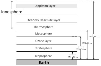
The gaseous envelope surrounding the earth is called it's atmosphere. The atmosphere contains 78% \[{{N}_{2}},\] 21% \[{{O}_{2}}\], and traces of other gases (like helium, krypton, \[C{{O}_{2}}\] etc.)
(1) Division of earth's atmosphere : Earth atmosphere has been divided into regions as shown.
(i) Troposphere : In this region, the temperature decreases with height from 290 K to 220 K.
(ii) Stratosphere : The temperature of stratosphere varies from 220 K to 200 K.
(iii) Mesosphere : In this region, the temperature falls to 180 K.
(iv) Ionosphere : Ionosphere is partly composed of charged particles, ions and electrons, while the rest of the atmosphere contains neutral molecules.
(v) Ozone layer absorbs most of the ultraviolet rays emitted by the sun.
(vi) Kennelly heaviside layer lies at about 110km from the earth's surface. In this layer concentration of electron is very high.
(vii) The ionosphere plays a vital role in the radio communication.
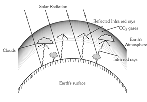
 (2) Green house effect : The warming of earth's atmosphere due to the infrared radiations reflected by low lying clouds and carbon dioxide in the atmosphere of earth is called green house effect.
 (3) Role of earth's atmosphere in propagation of radio waves
(i) Radio waves classification
(a) Very low frequency (VLF) \[\to \] 10 KHz to 30 KHz
(b) Low frequency (LF) \[\to \] 30 KHz to 300 KHz
(c) Medium frequency (MF) or medium wave (MW) \[\to \] 300 KHz to 3000 KHz
(d) High frequency (HF) or short wave (SW) \[\to \] 3 MHz to 30 MHz
(e) Very high frequency (VHF) \[\to \] 30 MHz to 300 MHz
(f) Ultra high frequency (UHF) \[\to \] 300 MHz to 3000 MHz
(g) Super high frequency or micro waves \[\to \] 3000 MHz to 300, 000 MHz
(ii) Amplitude modulated transmission : Radio waves having frequency less than or equal to 30 MHz form an amplitude modulation band (or AM band). The signals can be transmitted from one place to another place on earth's surface in two ways
(a) Ground wave propagation : The radio waves following the surface of the earth are called ground waves. (b) Sky wave propagation : The amplitude modulated radio waves which are reflected back by the ionosphere are called sky waves.
(iii) Frequency modulated (FM) transmission : Radio waves having frequencies between 80 MHz and 200 MHz form a frequency modulated bond. T.V. signals are normally frequency modulated.
(4) T.V. Signals
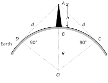
(i) T.V. signals are normally frequency modulated. So T.V. signals can be transmitted by using tall antennas.
(ii) Distance covered by the T.V. signals \[d=\sqrt{2hR}\]
(h = Height of the antenna, R = Radius of earth)
(iii) Area covered \[A=\pi {{d}^{2}}=2\pi hR\]
(iv) Population covered = Area \[\times \]Population density.
(3) Role of earth's atmosphere in propagation of radio waves
(i) Radio waves classification
(a) Very low frequency (VLF) \[\to \] 10 KHz to 30 KHz
(b) Low frequency (LF) \[\to \] 30 KHz to 300 KHz
(c) Medium frequency (MF) or medium wave (MW) \[\to \] 300 KHz to 3000 KHz
(d) High frequency (HF) or short wave (SW) \[\to \] 3 MHz to 30 MHz
(e) Very high frequency (VHF) \[\to \] 30 MHz to 300 MHz
(f) Ultra high frequency (UHF) \[\to \] 300 MHz to 3000 MHz
(g) Super high frequency or micro waves \[\to \] 3000 MHz to 300, 000 MHz
(ii) Amplitude modulated transmission : Radio waves having frequency less than or equal to 30 MHz form an amplitude modulation band (or AM band). The signals can be transmitted from one place to another place on earth's surface in two ways
(a) Ground wave propagation : The radio waves following the surface of the earth are called ground waves. (b) Sky wave propagation : The amplitude modulated radio waves which are reflected back by the ionosphere are called sky waves.
(iii) Frequency modulated (FM) transmission : Radio waves having frequencies between 80 MHz and 200 MHz form a frequency modulated bond. T.V. signals are normally frequency modulated.
(4) T.V. Signals
(i) T.V. signals are normally frequency modulated. So T.V. signals can be transmitted by using tall antennas.
(ii) Distance covered by the T.V. signals \[d=\sqrt{2hR}\]
(h = Height of the antenna, R = Radius of earth)
(iii) Area covered \[A=\pi {{d}^{2}}=2\pi hR\]
(iv) Population covered = Area \[\times \]Population density.
The whole orderly range of frequencies/wavelengths of the EM waves is known as the EM spectrum.
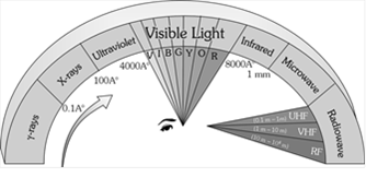 Uses of EM spectrum
(1) Speed : In free space it's speed
\[c=\frac{1}{\sqrt{{{\mu }_{0}}{{\varepsilon }_{0}}}}=\frac{{{E}_{0}}}{{{B}_{0}}}=3\times {{10}^{8}}m/s.\]
In medium \[v=\frac{1}{\sqrt{\mu \varepsilon }}\]; where \[{{\mu }_{0}}=\] Absolute permeability, \[{{\varepsilon }_{0}}=\] Absolute permittivity.
(2) Energy : The energy in an EM waves is divided equally between the electric and magnetic fields.
Energy density of electric field \[{{u}_{e}}=\frac{1}{2}{{\varepsilon }_{0}}{{E}^{2}}\], Energy density of magnetic field \[{{u}_{B}}=\frac{1}{2}\frac{{{B}^{2}}}{{{\mu }_{0}}}\]
The total energy per unit volume is \[u={{u}_{e}}+{{u}_{m}}\]\[=\frac{1}{2}{{\varepsilon }_{0}}{{E}^{2}}+\frac{1}{2}\frac{{{B}^{2}}}{{{\mu }_{0}}}\]. Also \[{{u}_{av}}=\frac{1}{2}{{\varepsilon }_{0}}E_{0}^{2}\]\[=\frac{B_{0}^{2}}{2{{\mu }_{0}}}\]
(3) Intensity (I) : The energy crossing per unit area per unit time, perpendicular to the direction of propagation of EM wave is called intensity.
i.e. \[I=\frac{\text{Total EM energy}}{\text{Surface area }\times \text{Time}}=\frac{\text{Total energy density}\times \text{Volume}}{\text{Surface area }\times \text{ Time}}\] \[\Rightarrow \]\[I={{u}_{av}}\times c=\frac{1}{2}{{\varepsilon }_{0}}E_{0}^{2}c=\frac{1}{2}\frac{B_{0}^{2}}{{{\mu }_{0}}}.c\frac{Watt}{{{m}^{2}}}.\]
(4) Momentum : EM waves also carries momentum, if a portion of EM wave of energy u propagating with speed c, then linear momentum \[=\frac{\text{Energy (}u\text{)}}{\text{Speed (}c\text{)}}\]
If wave incident on a completely absorbing surface then momentum delivered \[p=\frac{u}{c}\]. If wave incident on a totally reflecting surface then momentum delivered \[-p=\frac{2u}{c}\].
(5) Poynting vector\[(\vec{S}).\] : In EM waves, the rate of flow of energy crossing a unit area is described by the Poynting vector.
(i) It's unit is \[Watt/{{m}^{2}}\] and \[\vec{S}=\frac{1}{{{\mu }_{o}}}(\vec{E}\times \vec{B})={{c}^{2}}{{\varepsilon }_{0}}(\overrightarrow{E}\times \overrightarrow{B})\].
(ii) Because in EM waves \[\overrightarrow{E}\] and \[\overrightarrow{B}\] are perpendicular to each other, the magnitude of \[\overrightarrow{S}\] is \[\,|\vec{S}|\,=\frac{1}{{{\mu }_{0}}}E\,B\,\sin {{90}^{o}}=\frac{EB}{{{\mu }_{0}}}=\frac{{{E}^{2}}}{\mu \,C}\].
(iii) The direction of \[\overrightarrow{S}\] does not oscillate but it's magnitude varies between zero and a maximum \[\left( {{S}_{\max }}=\frac{{{E}_{0}}{{B}_{0}}}{{{\mu }_{0}}} \right)\] each quarter of a period.
(iv) Average value of poynting vector is given by \[\overline{S}=\frac{1}{2{{\mu }_{0}}}{{E}_{0}}{{B}_{0}}=\frac{1}{2}{{\varepsilon }_{0}}E_{0}^{2}c=\frac{cB_{0}^{2}}{2{{\mu }_{0}}}\]
The direction of the poynting vector \[\overrightarrow{S}\] at any point gives the wave's direction of travel and direction of energy transport the point.
(6) Radiation pressure : Is the momentum imparted per second pre unit area. On which the light falls.
For a perfectly reflecting surface \[{{P}_{r}}=\frac{2S}{c}\]; S = Poynting vector; c = Speed of light
For a perfectly absorbing surface \[{{P}_{a}}=\frac{S}{c}.\]
(7) Wave impedance (Z) : The medium offers hindrance to the propagation of wave. Such hindrance is called wave impedance and it is given by \[Z=\sqrt{\frac{\mu }{\varepsilon }}=\sqrt{\frac{{{\mu }_{r}}}{{{\varepsilon }_{r}}}}\sqrt{\frac{{{\mu }_{0}}}{{{\varepsilon }_{0}}}}\]
For vacuum or free space \[Z=\sqrt{\frac{{{\mu }_{0}}}{{{\varepsilon }_{0}}}}=376.6\,\Omega .\]
(1) A charge oscillating harmonically is a source of EM waves of same frequency.
(2) A simple LC oscillator and energy source can produce waves of desired frequency \[\left( \nu =\frac{1}{2\pi \sqrt{LC}} \right)\].
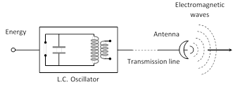 (3) The EM Waves are transverse in nature. They do not require any material medium for their propagation.
Hertz experiment based on the fact that a oscillating charge is accelerating continuously, it will radiate electromagnetic waves continuously. In the following figure
(1) The metallic plates (\[{{P}_{1}}\] and \[{{P}_{2}}\]) acts as a capacitor.
(2) The wires connecting spheres \[{{S}_{1}}\] and \[{{S}_{2}}\] to the plates provide a low inductance.
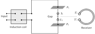 (3) When a high voltage is applied across metallic plates these plates get discharged by sparking across the narrow gap. The spark will give rise to oscillations which in turn send out electromagnetic waves. Frequency of these wave is given by \[\nu =\frac{1}{2\pi \sqrt{LC}}\]
The succession of sparks send out a train of such waves which are received by the receiver.
(3) When a high voltage is applied across metallic plates these plates get discharged by sparking across the narrow gap. The spark will give rise to oscillations which in turn send out electromagnetic waves. Frequency of these wave is given by \[\nu =\frac{1}{2\pi \sqrt{LC}}\]
The succession of sparks send out a train of such waves which are received by the receiver.
(1) Maxwell : Was the first to predict the EM wave.
(2) Hertz : Produced and detected electromagnetic waves experimentally at wavelengths of 6 m.
(3) J.C. Bose : Produced EM waves of wavelength ranging from 5mm to 25 mm.
(4) Marconi : Successfully transmitted the EM waves up to a few kilometer. Marconi discovered that if one of the spark gap terminals is connected to an antenna and the other terminal is Earthed, the electromagnetic waves radiated could go upto several kilometers.
(1) Ampere's Circuital law : According to this law the line integral of magnetic field along any closed path or circuit is \[{{\mu }_{0}}\] times the total current threading the closed circuit i.e., \[\oint{\overset{\to }{\mathop{B}}\,}.\overset{\to }{\mathop{dl}}\,={{\mu }_{0}}i\]
(2) Inconsistency of Ampere's law : Maxwell explained that Ampere's law is valid only for steady current or when the electric field does not change with time. To see this inconsistency consider a parallel plate capacitor being charged by a battery. During the charging time varying current flows through connecting wires.
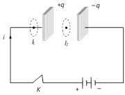 Applying Ampere's law for loop \[{{l}_{1}}\] and \[{{l}_{2}}\] \[\oint{\underset{{{l}_{1}}}{\mathop{{}}}\,\overset{\to }{\mathop{B}}\,}.\overset{\to }{\mathop{dl}}\,={{\mu }_{0}}i\]
But \[\oint{\underset{{{l}_{2}}}{\mathop{{}}}\,\overset{\to }{\mathop{B}}\,}.\overset{\to }{\mathop{dl}}\,=0\] (Since no current flows through the region between the plates). But practically it is observed that there is a magnetic field between the plates. Hence Ampere's law fails
i.e. \[\oint{\underset{{{l}_{1}}}{\mathop{{}}}\,\overset{\to }{\mathop{B}}\,}.\overset{\to }{\mathop{dl}}\,\ne {{\mu }_{0}}i\].
(3) Modified Ampere's Circuital law or Ampere- Maxwell's Circuital law : Maxwell assumed that some sort of current must be flowing between the capacitor plates during charging process. He named it displacement current. Hence modified law is as follows
\[\oint{\overset{\to }{\mathop{B}}\,}.\overset{\to }{\mathop{dl}}\,={{\mu }_{0}}({{i}_{c}}+{{i}_{d}})\ \]or \[\oint{\overset{\to }{\mathop{B}}\,}.\overset{\to }{\mathop{dl}}\,={{\mu }_{0}}({{i}_{c}}+{{\varepsilon }_{0}}\frac{d{{\varphi }_{E}}}{dt})\]
where \[{{i}_{c}}=\] conduction current = current due to flow of charges in a conductor and
\[{{i}_{d}}=\] Displacement current = \[{{\varepsilon }_{0}}\frac{d{{\varphi }_{E}}}{dt}\] = current due to the changing electric field between the plates of the capacitor
(4) Maxwell's equations
(i) \[\oint{\underset{s}{\mathop{{}}}\,\overset{\to }{\mathop{E}}\,}.\overset{\to }{\mathop{ds}}\,=\frac{q}{{{\varepsilon }_{0}}}\] (Gauss's law in electrostatics)
(ii) \[\oint{\underset{s}{\mathop{{}}}\,\overset{\to }{\mathop{B}}\,}.\overset{\to }{\mathop{ds}}\,=0\] (Gauss's law in magnetism)
(iii) \[\oint_{{}}{\overset{\to }{\mathop{B}}\,\,.\,\overset{\to }{\mathop{dl}}\,}\,=-\frac{d{{\varphi }_{B}}}{dt}\] (Faraday's law of EMI)
(iv) \[\oint{\overset{\to }{\mathop{B}}\,\,\,\overset{\to }{\mathop{dl}}\,}={{\mu }_{o}}({{i}_{c}}+{{\varepsilon }_{o}}\frac{d{{\varphi }_{E}}}{dt}\] (Maxwell- Ampere's Circuital law)
Applying Ampere's law for loop \[{{l}_{1}}\] and \[{{l}_{2}}\] \[\oint{\underset{{{l}_{1}}}{\mathop{{}}}\,\overset{\to }{\mathop{B}}\,}.\overset{\to }{\mathop{dl}}\,={{\mu }_{0}}i\]
But \[\oint{\underset{{{l}_{2}}}{\mathop{{}}}\,\overset{\to }{\mathop{B}}\,}.\overset{\to }{\mathop{dl}}\,=0\] (Since no current flows through the region between the plates). But practically it is observed that there is a magnetic field between the plates. Hence Ampere's law fails
i.e. \[\oint{\underset{{{l}_{1}}}{\mathop{{}}}\,\overset{\to }{\mathop{B}}\,}.\overset{\to }{\mathop{dl}}\,\ne {{\mu }_{0}}i\].
(3) Modified Ampere's Circuital law or Ampere- Maxwell's Circuital law : Maxwell assumed that some sort of current must be flowing between the capacitor plates during charging process. He named it displacement current. Hence modified law is as follows
\[\oint{\overset{\to }{\mathop{B}}\,}.\overset{\to }{\mathop{dl}}\,={{\mu }_{0}}({{i}_{c}}+{{i}_{d}})\ \]or \[\oint{\overset{\to }{\mathop{B}}\,}.\overset{\to }{\mathop{dl}}\,={{\mu }_{0}}({{i}_{c}}+{{\varepsilon }_{0}}\frac{d{{\varphi }_{E}}}{dt})\]
where \[{{i}_{c}}=\] conduction current = current due to flow of charges in a conductor and
\[{{i}_{d}}=\] Displacement current = \[{{\varepsilon }_{0}}\frac{d{{\varphi }_{E}}}{dt}\] = current due to the changing electric field between the plates of the capacitor
(4) Maxwell's equations
(i) \[\oint{\underset{s}{\mathop{{}}}\,\overset{\to }{\mathop{E}}\,}.\overset{\to }{\mathop{ds}}\,=\frac{q}{{{\varepsilon }_{0}}}\] (Gauss's law in electrostatics)
(ii) \[\oint{\underset{s}{\mathop{{}}}\,\overset{\to }{\mathop{B}}\,}.\overset{\to }{\mathop{ds}}\,=0\] (Gauss's law in magnetism)
(iii) \[\oint_{{}}{\overset{\to }{\mathop{B}}\,\,.\,\overset{\to }{\mathop{dl}}\,}\,=-\frac{d{{\varphi }_{B}}}{dt}\] (Faraday's law of EMI)
(iv) \[\oint{\overset{\to }{\mathop{B}}\,\,\,\overset{\to }{\mathop{dl}}\,}={{\mu }_{o}}({{i}_{c}}+{{\varepsilon }_{o}}\frac{d{{\varphi }_{E}}}{dt}\] (Maxwell- Ampere's Circuital law) Current Affairs CategoriesArchive
Trending Current Affairs


You need to login to perform this action. |

