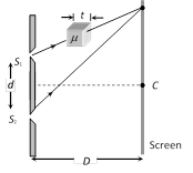
 (1) \[\text{Fringe shift}=\frac{D}{d}(\mu -1)\,t=\frac{\beta }{\lambda }(\mu -1)\,t\]
(2) Additional path difference\[=(\mu -1)t\]
(3) If shift is equivalent to n fringes then \[n=\frac{(\mu -1)\,t}{\lambda }\] or \[t=\frac{n\lambda }{(\mu -1)}\]
(4) Shift is independent of the order of fringe (i.e. shift of zero order maxima = shift of nth order maxima.
(5) Shift is independent of wavelength.
(1) \[\text{Fringe shift}=\frac{D}{d}(\mu -1)\,t=\frac{\beta }{\lambda }(\mu -1)\,t\]
(2) Additional path difference\[=(\mu -1)t\]
(3) If shift is equivalent to n fringes then \[n=\frac{(\mu -1)\,t}{\lambda }\] or \[t=\frac{n\lambda }{(\mu -1)}\]
(4) Shift is independent of the order of fringe (i.e. shift of zero order maxima = shift of nth order maxima.
(5) Shift is independent of wavelength. 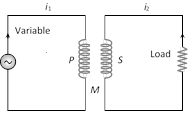 (1) Coefficient of mutual induction : Total flux linked with the secondary due to current in the primary is \[{{N}_{2}}{{\phi }_{2}}\] and \[{{N}_{2}}{{\phi }_{2}}\,\propto {{i}_{1}}\Rightarrow {{N}_{2}}{{\phi }_{2}}=M{{i}_{1}}\] where \[{{N}_{1}}-\]Number of turns in primary; \[{{N}_{2}}-\]Number of turns in secondary; \[{{\phi }_{2}}-\]Flux linked with each turn of secondary; \[{{i}_{1}}-\]Current flowing through primary; M-Coefficient of mutual induction or mutual inductance.
(2) According to Faraday's second law emf induces in secondary \[{{e}_{2}}=-{{N}_{2}}\frac{d{{\varphi }_{2}}}{dt}\]; \[{{e}_{\mathbf{2}}}=-M\frac{d{{i}_{\mathbf{1}}}}{dt}\]
(3) If \[\frac{d{{i}_{1}}}{dt}=\frac{1Amp}{sec}\] then \[|{{e}_{2}}|=M\].
Hence coefficient of mutual induction is equal to the emf induced in the secondary coil when rate of change of current in primary coil is unity.
(4) Units and dimensional formula of M : Similar to self-inductance (L)
(5) Dependence of mutual inductance
(i) Number of turns \[({{N}_{1}},\,{{N}_{2}})\] of both coils
(ii) Coefficient of self inductances \[({{L}_{1}},\,{{L}_{2}})\] of both the coils
(iii) Area of cross-section of coils
(iv) Magnetic permeability of medium between the coils \[({{\mu }_{r}})\] or nature of material on which two coils are wound (v) Distance between two coils (As d increases so M decreases)
(vi) Orientation between primary and secondary coil (for \[{{90}^{o}}\] orientation no flux relation \[M=0\])
(vii) Coupling factor 'K' between primary and secondary coil
(6) Relation between M, \[{{L}_{1}}\] and \[{{L}_{2}}\]: For two magnetically coupled coils \[M=k\sqrt{{{L}_{1}}{{L}_{2}}}\]; where k ' coefficient of coupling or coupling factor which is defined as
\[k=\frac{\text{Magnetic flux linked in secondary}}{\text{Magnetic flux linked in primary}}\]; \[0\le k\le 1\]
(1) Coefficient of mutual induction : Total flux linked with the secondary due to current in the primary is \[{{N}_{2}}{{\phi }_{2}}\] and \[{{N}_{2}}{{\phi }_{2}}\,\propto {{i}_{1}}\Rightarrow {{N}_{2}}{{\phi }_{2}}=M{{i}_{1}}\] where \[{{N}_{1}}-\]Number of turns in primary; \[{{N}_{2}}-\]Number of turns in secondary; \[{{\phi }_{2}}-\]Flux linked with each turn of secondary; \[{{i}_{1}}-\]Current flowing through primary; M-Coefficient of mutual induction or mutual inductance.
(2) According to Faraday's second law emf induces in secondary \[{{e}_{2}}=-{{N}_{2}}\frac{d{{\varphi }_{2}}}{dt}\]; \[{{e}_{\mathbf{2}}}=-M\frac{d{{i}_{\mathbf{1}}}}{dt}\]
(3) If \[\frac{d{{i}_{1}}}{dt}=\frac{1Amp}{sec}\] then \[|{{e}_{2}}|=M\].
Hence coefficient of mutual induction is equal to the emf induced in the secondary coil when rate of change of current in primary coil is unity.
(4) Units and dimensional formula of M : Similar to self-inductance (L)
(5) Dependence of mutual inductance
(i) Number of turns \[({{N}_{1}},\,{{N}_{2}})\] of both coils
(ii) Coefficient of self inductances \[({{L}_{1}},\,{{L}_{2}})\] of both the coils
(iii) Area of cross-section of coils
(iv) Magnetic permeability of medium between the coils \[({{\mu }_{r}})\] or nature of material on which two coils are wound (v) Distance between two coils (As d increases so M decreases)
(vi) Orientation between primary and secondary coil (for \[{{90}^{o}}\] orientation no flux relation \[M=0\])
(vii) Coupling factor 'K' between primary and secondary coil
(6) Relation between M, \[{{L}_{1}}\] and \[{{L}_{2}}\]: For two magnetically coupled coils \[M=k\sqrt{{{L}_{1}}{{L}_{2}}}\]; where k ' coefficient of coupling or coupling factor which is defined as
\[k=\frac{\text{Magnetic flux linked in secondary}}{\text{Magnetic flux linked in primary}}\]; \[0\le k\le 1\]
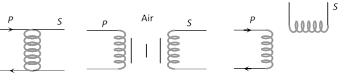 (A) k = 1 (B) 0 < k < 1 (C) k = 0
(7) The various formulae for M :
(A) k = 1 (B) 0 < k < 1 (C) k = 0
(7) The various formulae for M :
| Condition | Figure |
| Two concentric coplaner circular coils \[M=\frac{\pi {{\mu }_{0}}{{N}_{1}}{{N}_{2}}{{r}^{2}}}{2R}\] |  |
| more...
(1) The initial phase difference between the interfering waves must remain constant. Otherwise the interference will not be sustained.
(2) The frequency and wavelengths of two waves should be equal. If not the phase difference will not remain constant and so the interference will not be sustained.
(3) The light must be monochromatic. This eliminates overlapping of patterns as each wavelength corresponds to one interference pattern.
(4) The amplitudes of the waves must be equal. This improves contrast with \[{{I}_{\max }}=4{{I}_{0}}\] and \[{{I}_{\min }}=0.\]
(5) The sources must be close to each other. Otherwise due to small fringe width \[\left( \beta \propto \frac{1}{d} \right)\] the eye can not resolve fringes resulting in uniform illumination.
(1) Path difference : Path difference between the interfering waves meeting at a point P on the screen is given by
\[\Delta ={{\Delta }_{i}}+{{\Delta }_{f}}\]; where \[{{\Delta }_{i}}=\]initial path difference between the waves before the slits and \[{{\Delta }_{f}}=\]path difference between the waves after emerging from the slits. In this case \[{{\Delta }_{i}}=0\] (Commonly used condition). So \[\Delta ={{\Delta }_{f}}=\frac{xd}{D}=d\sin \theta \]
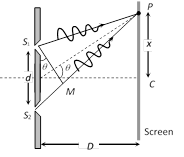 where \[x\] is the position of point P from central maxima.
For maxima at P : \[\Delta =n\lambda \]; where \[n=0,\,\,\pm 1,\,\pm 2,\,...\]
and For minima at P : \[\Delta =\frac{(2n-1)\lambda }{2}\]; where \[n=\,\,\pm 1,\,\pm 2,\,...\]
(2) Location of fringe : Position of nth bright fringe from central maxima \[{{x}_{n}}=\frac{n\lambda D}{d}=n\beta \]; \[n=0,\,1,\,2\,....\]
Position of nth dark fringe from central maxima
\[{{x}_{n}}=\frac{(2n-1)\,\lambda D}{2d}=\frac{(2n-1)\,\beta }{2}\]; \[n=1,\,2,3\,....\]
(3) Fringe width \[(\beta )\]: The separation between any two consecutive bright or dark fringes is called fringe width. In YDSE all fringes are of equal width. Fringe width \[\beta =\frac{\lambda \,D}{d}\].
where \[x\] is the position of point P from central maxima.
For maxima at P : \[\Delta =n\lambda \]; where \[n=0,\,\,\pm 1,\,\pm 2,\,...\]
and For minima at P : \[\Delta =\frac{(2n-1)\lambda }{2}\]; where \[n=\,\,\pm 1,\,\pm 2,\,...\]
(2) Location of fringe : Position of nth bright fringe from central maxima \[{{x}_{n}}=\frac{n\lambda D}{d}=n\beta \]; \[n=0,\,1,\,2\,....\]
Position of nth dark fringe from central maxima
\[{{x}_{n}}=\frac{(2n-1)\,\lambda D}{2d}=\frac{(2n-1)\,\beta }{2}\]; \[n=1,\,2,3\,....\]
(3) Fringe width \[(\beta )\]: The separation between any two consecutive bright or dark fringes is called fringe width. In YDSE all fringes are of equal width. Fringe width \[\beta =\frac{\lambda \,D}{d}\].
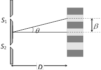 and angular fringe width \[\theta =\frac{\lambda }{d}=\frac{\beta }{D}\]
(4) In YDSE, if \[{{n}_{1}}\] fringes are visible in a field of view with light of wavelength \[{{\lambda }_{1}}\], while \[{{n}_{1}}\] with light of wavelength \[{{\lambda }_{2}}\] in the same field, then \[{{n}_{\mathbf{1}}}{{\lambda }_{\mathbf{1}}}={{n}_{\mathbf{2}}}{{\lambda }_{\mathbf{2}}}\].
(5) Separation \[(\Delta x)\] between fringes
(i) Between nth bright and mth bright fringes \[(n>m)\] \[\Delta x=(n-m)\beta \]
(ii) Between nth bright and mth dark fringe
(a) If \[n>m\] then \[\Delta x=\left( n-m+\frac{1}{2} \right)\beta \]
(b) If \[n<m\] then \[\Delta x=\left( m-n-\frac{1}{2} \right)\beta \]
(6) Identification of central bright fringe : To identify central bright fringe, monochromatic light is replaced by white light. Due to overlapping central maxima will be white with red edges. On the other side of it we shall get a few coloured band and then uniform illumination.
If the whole YDSE set up is taken in another medium then \[\lambda \] changes so \[\beta \] changes
e.g. in water \[{{\lambda }_{w}}=\frac{{{\lambda }_{a}}}{{{\mu }_{w}}}\Rightarrow {{\beta }_{w}}=\frac{{{\beta }_{a}}}{{{\mu }_{w}}}=\frac{3}{4}{{\beta }_{a}}\]
and angular fringe width \[\theta =\frac{\lambda }{d}=\frac{\beta }{D}\]
(4) In YDSE, if \[{{n}_{1}}\] fringes are visible in a field of view with light of wavelength \[{{\lambda }_{1}}\], while \[{{n}_{1}}\] with light of wavelength \[{{\lambda }_{2}}\] in the same field, then \[{{n}_{\mathbf{1}}}{{\lambda }_{\mathbf{1}}}={{n}_{\mathbf{2}}}{{\lambda }_{\mathbf{2}}}\].
(5) Separation \[(\Delta x)\] between fringes
(i) Between nth bright and mth bright fringes \[(n>m)\] \[\Delta x=(n-m)\beta \]
(ii) Between nth bright and mth dark fringe
(a) If \[n>m\] then \[\Delta x=\left( n-m+\frac{1}{2} \right)\beta \]
(b) If \[n<m\] then \[\Delta x=\left( m-n-\frac{1}{2} \right)\beta \]
(6) Identification of central bright fringe : To identify central bright fringe, monochromatic light is replaced by white light. Due to overlapping central maxima will be white with red edges. On the other side of it we shall get a few coloured band and then uniform illumination.
If the whole YDSE set up is taken in another medium then \[\lambda \] changes so \[\beta \] changes
e.g. in water \[{{\lambda }_{w}}=\frac{{{\lambda }_{a}}}{{{\mu }_{w}}}\Rightarrow {{\beta }_{w}}=\frac{{{\beta }_{a}}}{{{\mu }_{w}}}=\frac{3}{4}{{\beta }_{a}}\]
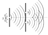
Monochromatic light (single wavelength) falls on two narrow slits \[{{S}_{1}}\] and \[{{S}_{2}}\] which are very close together acts as two coherent sources, when waves coming from two coherent sources \[({{S}_{1}},\,{{S}_{ & 2}})\] superimposes on each other, an interference pattern is obtained on the screen. In YDSE alternate bright and dark bands obtained on the screen. These bands are called Fringes.
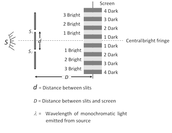 (1) Central fringe is always bright, because at central position \[\varphi ={{0}^{o}}\]or \[\Delta =0\]
(2) The fringe pattern obtained due to a slit is more bright than that due to a point.
(3) If the slit widths are unequal, the minima will not be complete dark. For very large width uniform illumination occurs.
(4) If one slit is illuminated with red light and the other slit is illuminated with blue light, no interference pattern is observed on the screen.
(5) If the two coherent sources consist of object and it's reflected image, the central fringe is dark instead of bright one.
(1) Central fringe is always bright, because at central position \[\varphi ={{0}^{o}}\]or \[\Delta =0\]
(2) The fringe pattern obtained due to a slit is more bright than that due to a point.
(3) If the slit widths are unequal, the minima will not be complete dark. For very large width uniform illumination occurs.
(4) If one slit is illuminated with red light and the other slit is illuminated with blue light, no interference pattern is observed on the screen.
(5) If the two coherent sources consist of object and it's reflected image, the central fringe is dark instead of bright one.
When two waves of exactly same frequency (coming from two coherent sources) travels in a medium, in the same direction simultaneously then due to their superposition, at some points intensity of light is maximum while at some other points intensity is minimum. This phenomenon is called Interference of light. It is of following two types
 (1) Constructive interference : When the waves meets a point with same phase, constructive interference is obtained at that point (i.e. maximum light)
(i) Phase difference between the waves at the point of observation \[\varphi ={{0}^{o}}\,\text{or}\,2n\pi \]
(ii) Path difference between the waves at the point of observation \[\Delta =n\lambda \](i.e. even multiple of \[\lambda /2\])
(iii) Resultant amplitude at the point of observation will be maximum \[{{A}_{\max }}={{a}_{1}}+{{a}_{2}}\]
If \[{{a}_{1}}={{a}_{2}}={{a}_{0}}\Rightarrow {{A}_{\max }}=2{{a}_{0}}\]
(iv) Resultant intensity at the point of observation will be maximum \[{{I}_{\max }}={{I}_{1}}+{{I}_{2}}+2\sqrt{{{I}_{1}}{{I}_{2}}}\] \[={{\left( \sqrt{{{I}_{1}}}+\sqrt{{{I}_{2}}} \right)}^{2}}\]
If \[{{I}_{1}}={{I}_{2}}={{I}_{0}}\Rightarrow {{I}_{\max }}=4{{I}_{0}}\]
(2) Destructive interference : When the wave meets a point with opposite phase, destructive interference is obtained at that point (i.e. minimum light)
(i) Phase difference \[\varphi ={{180}^{o}}\text{or}\,(2n-1)\,\pi \,;\,\]\[n=1,\,\,2,\,...\]
or \[(2n+1)\,\pi \,;\]\[n=0,1,2.....\]
(ii) Path difference \[\Delta =(2n-1)\frac{\lambda }{2}\] (i.e. odd multiple of \[\lambda /2\])
(iii) Resultant amplitude at the point of observation will be minimum \[{{A}_{\min }}={{a}_{1}}-{{a}_{2}}\]
If \[{{a}_{1}}={{a}_{2}}\Rightarrow {{A}_{\min }}=0\]
(iv) Resultant intensity at the point of observation will be minimum \[{{I}_{\min }}={{I}_{1}}+{{I}_{2}}-2\sqrt{{{I}_{1}}{{I}_{2}}}\]\[={{\left( \sqrt{{{I}_{1}}}-\sqrt{{{I}_{2}}} \right)}^{2}}\] If \[{{I}_{1}}={{I}_{2}}={{I}_{0}}\Rightarrow {{I}_{\min }}=0\]
(3) Super position of waves of random phase difference : When two waves (or more waves) having random phase difference between them super impose, then no interference pattern is produced. Then the resultant intensity is just the sum of the two intensities. \[I={{I}_{1}}+{{I}_{2}}\]
(1) Constructive interference : When the waves meets a point with same phase, constructive interference is obtained at that point (i.e. maximum light)
(i) Phase difference between the waves at the point of observation \[\varphi ={{0}^{o}}\,\text{or}\,2n\pi \]
(ii) Path difference between the waves at the point of observation \[\Delta =n\lambda \](i.e. even multiple of \[\lambda /2\])
(iii) Resultant amplitude at the point of observation will be maximum \[{{A}_{\max }}={{a}_{1}}+{{a}_{2}}\]
If \[{{a}_{1}}={{a}_{2}}={{a}_{0}}\Rightarrow {{A}_{\max }}=2{{a}_{0}}\]
(iv) Resultant intensity at the point of observation will be maximum \[{{I}_{\max }}={{I}_{1}}+{{I}_{2}}+2\sqrt{{{I}_{1}}{{I}_{2}}}\] \[={{\left( \sqrt{{{I}_{1}}}+\sqrt{{{I}_{2}}} \right)}^{2}}\]
If \[{{I}_{1}}={{I}_{2}}={{I}_{0}}\Rightarrow {{I}_{\max }}=4{{I}_{0}}\]
(2) Destructive interference : When the wave meets a point with opposite phase, destructive interference is obtained at that point (i.e. minimum light)
(i) Phase difference \[\varphi ={{180}^{o}}\text{or}\,(2n-1)\,\pi \,;\,\]\[n=1,\,\,2,\,...\]
or \[(2n+1)\,\pi \,;\]\[n=0,1,2.....\]
(ii) Path difference \[\Delta =(2n-1)\frac{\lambda }{2}\] (i.e. odd multiple of \[\lambda /2\])
(iii) Resultant amplitude at the point of observation will be minimum \[{{A}_{\min }}={{a}_{1}}-{{a}_{2}}\]
If \[{{a}_{1}}={{a}_{2}}\Rightarrow {{A}_{\min }}=0\]
(iv) Resultant intensity at the point of observation will be minimum \[{{I}_{\min }}={{I}_{1}}+{{I}_{2}}-2\sqrt{{{I}_{1}}{{I}_{2}}}\]\[={{\left( \sqrt{{{I}_{1}}}-\sqrt{{{I}_{2}}} \right)}^{2}}\] If \[{{I}_{1}}={{I}_{2}}={{I}_{0}}\Rightarrow {{I}_{\min }}=0\]
(3) Super position of waves of random phase difference : When two waves (or more waves) having random phase difference between them super impose, then no interference pattern is produced. Then the resultant intensity is just the sum of the two intensities. \[I={{I}_{1}}+{{I}_{2}}\]
The phase relationship between two light waves can very from time to time and from point to point in space. The property of definite phase relationship is called coherence.
(1) Temporal coherence : In a light source a light wave (photon) is produced when an excited atom goes to the ground state and emits light.
(i) The duration of this transition is about \[{{10}^{-9}}\] to \[{{10}^{-10}}\] sec. Thus the emitted wave remains sinusoidal for this much time. This time is known as coherence time \[({{\tau }_{c}})\].
(ii) Definite phase relationship is maintained for a length \[L=c{{\tau }_{c}}\] called coherence length. For neon \[\lambda =6328\,\,\overset{\text{o}}{\mathop{\text{A}}}\,,\,\,{{\tau }_{c}}\approx {{10}^{-10}}\] sec and L = 0.03 m.
For cadmium \[\lambda =6438\,\,\overset{\text{o}}{\mathop{\text{A}}}\,,\,\,{{\tau }_{c}}={{10}^{-9}}\] sec and L = 0.3 m
For Laser \[{{\tau }_{c}}={{10}^{-5}}\] sec and L = 3 km
(iii) The spectral lines width \[\Delta \lambda \] is related to coherence length L and coherence time \[{{\tau }_{c}}\]. \[\Delta \lambda \approx \frac{{{\lambda }^{2}}}{c{{\tau }_{c}}}\] or \[\Delta \lambda \approx \frac{{{\lambda }^{2}}}{L}\]
(2) Spatial coherence : Two points in space are said to be spatially coherence if the waves reaching there maintains a constant phase difference
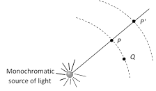 Points P and Q are at the same distance from S, they will always be having the same phase. Points P and \[P'\] will be spatially coherent if the distance between P and \[P'\] is much less than the coherence length i.e. \[PP'<<c{{\tau }_{c}}\]
(3) Methods of obtaining coherent sources : Two coherent sources are produced from a single source of light by two methods (i) By division of wavefront and (ii) By division of amplitude
(i) Division of wave front : The wave front emitted by a narrow source is divided in two parts by reflection, refraction or diffraction.
The coherent sources so obtained are imaginary. There produced in Fresnel's biprism, Llyod's mirror Youngs' double slit etc.
Points P and Q are at the same distance from S, they will always be having the same phase. Points P and \[P'\] will be spatially coherent if the distance between P and \[P'\] is much less than the coherence length i.e. \[PP'<<c{{\tau }_{c}}\]
(3) Methods of obtaining coherent sources : Two coherent sources are produced from a single source of light by two methods (i) By division of wavefront and (ii) By division of amplitude
(i) Division of wave front : The wave front emitted by a narrow source is divided in two parts by reflection, refraction or diffraction.
The coherent sources so obtained are imaginary. There produced in Fresnel's biprism, Llyod's mirror Youngs' double slit etc.
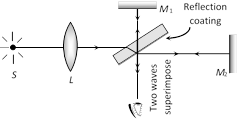
 (ii) Division of amplitude : In this arrangement light wave is partly reflected (50%) and partly transmitted (50%) to produced two light rays.
The amplitude of wave emitted by an extend source of light is divided in two parts by partial reflection and partial refraction.
The coherent sources obtained are real and are obtained in Newton's rings, Michelson's interferrometer, colours in thin films.
(ii) Division of amplitude : In this arrangement light wave is partly reflected (50%) and partly transmitted (50%) to produced two light rays.
The amplitude of wave emitted by an extend source of light is divided in two parts by partial reflection and partial refraction.
The coherent sources obtained are real and are obtained in Newton's rings, Michelson's interferrometer, colours in thin films.
Let us consider two waves that have the same frequency but have a certain fixed (constant) phase difference between them. Their super position shown below
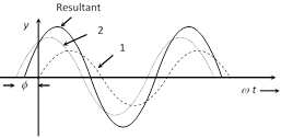 Let the two waves are
\[{{y}_{1}}={{a}_{1}}\sin \,\omega \,t\] and \[{{y}_{2}}={{a}_{2}}\sin \,(\omega \,t+\varphi )\]
where \[{{a}_{1}},\,{{a}_{2}}=\] Individual amplitudes,
\[\phi =\] Phase difference between the waves at an instant when they are meeting a point.
(1) Resultant amplitude : The resultant wave can be written as \[y=A\,\,\sin \,(\omega t+\theta )\]
where A = resultant amplitude \[=\sqrt{a_{1}^{2}+a_{2}^{2}+2{{a}_{1}}{{a}_{2}}\cos \varphi }\]
(2) Resultant intensity : As we know intensity \[\propto {{(\text{Amplitude})}^{2}}\]
\[\Rightarrow \] \[{{I}_{1}}=ka_{1}^{2},\,{{I}_{2}}=ka_{2}^{2}\] and \[I=k{{A}^{2}}\] (k is a proportionality constant). Resultant intensity \[I={{I}_{1}}+{{I}_{2}}+2\sqrt{{{I}_{1}}{{I}_{2}}}\cos \varphi \]
For two identical source \[{{I}_{1}}={{I}_{2}}={{I}_{0}}\]\[\Rightarrow \]\[I={{I}_{0}}+{{I}_{0}}+2\sqrt{{{I}_{0}}{{I}_{0}}}\cos \varphi \]
\[=4{{I}_{0}}{{\cos }^{2}}\frac{\varphi }{2}\] \[[1+\cos \theta =2{{\cos }^{2}}\frac{\theta }{2}]\]
Let the two waves are
\[{{y}_{1}}={{a}_{1}}\sin \,\omega \,t\] and \[{{y}_{2}}={{a}_{2}}\sin \,(\omega \,t+\varphi )\]
where \[{{a}_{1}},\,{{a}_{2}}=\] Individual amplitudes,
\[\phi =\] Phase difference between the waves at an instant when they are meeting a point.
(1) Resultant amplitude : The resultant wave can be written as \[y=A\,\,\sin \,(\omega t+\theta )\]
where A = resultant amplitude \[=\sqrt{a_{1}^{2}+a_{2}^{2}+2{{a}_{1}}{{a}_{2}}\cos \varphi }\]
(2) Resultant intensity : As we know intensity \[\propto {{(\text{Amplitude})}^{2}}\]
\[\Rightarrow \] \[{{I}_{1}}=ka_{1}^{2},\,{{I}_{2}}=ka_{2}^{2}\] and \[I=k{{A}^{2}}\] (k is a proportionality constant). Resultant intensity \[I={{I}_{1}}+{{I}_{2}}+2\sqrt{{{I}_{1}}{{I}_{2}}}\cos \varphi \]
For two identical source \[{{I}_{1}}={{I}_{2}}={{I}_{0}}\]\[\Rightarrow \]\[I={{I}_{0}}+{{I}_{0}}+2\sqrt{{{I}_{0}}{{I}_{0}}}\cos \varphi \]
\[=4{{I}_{0}}{{\cos }^{2}}\frac{\varphi }{2}\] \[[1+\cos \theta =2{{\cos }^{2}}\frac{\theta }{2}]\]
(1) Phase : The argument of sine or cosine in the expression for displacement of a wave is defined as the phase. For displacement \[y=a\sin \omega t;\] term \[\omega t=\] phase or instantaneous phase.
(2) Phase difference \[(\phi )\]: The difference between the phases of two waves at a point is called phase difference i.e. if \[{{y}_{1}}={{a}_{1}}\sin \,\omega \,t\] and \[{{y}_{2}}={{a}_{2}}\sin \,(\omega \,t+\varphi )\] so phase difference \[=\phi \]
(3) Path difference \[(\Delta )\]: The difference in path length?s of two waves meeting at a point is called path difference between the waves at that point. Also \[\Delta =\frac{\lambda }{\mathbf{2}\,\pi }\times \varphi \]
(4) Time difference (T.D.) : Time difference between the waves meeting at a point is \[T.D.=\frac{T}{\mathbf{2}\pi }\times \varphi \]
Current Affairs CategoriesArchive
Trending Current Affairs


You need to login to perform this action. |

