 Electromagnetic waves which are used in Radio, Television and other communication system are radio waves and microwaves.
The radio waves emitted from a transmitter anteena can reach the receiver antenna by the following mode of operation.
Electromagnetic waves which are used in Radio, Television and other communication system are radio waves and microwaves.
The radio waves emitted from a transmitter anteena can reach the receiver antenna by the following mode of operation.
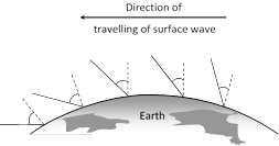 (v) Ground wave propagation can be sustained only at low frequencies \[\left( \tilde{\ }500\,kHz\,\,\text{to }1500kHz \right)\] or for radio broadcast at long wavelengths.
(2) Sky wave propagation
(i) These are the waves which are reflected back to the earth by ionosphere.
Ionosphere is a layer of atmosphere having charged particles, ions and electrons and extended above 80 km ? 300 km from the earth's surface.
(v) Ground wave propagation can be sustained only at low frequencies \[\left( \tilde{\ }500\,kHz\,\,\text{to }1500kHz \right)\] or for radio broadcast at long wavelengths.
(2) Sky wave propagation
(i) These are the waves which are reflected back to the earth by ionosphere.
Ionosphere is a layer of atmosphere having charged particles, ions and electrons and extended above 80 km ? 300 km from the earth's surface.
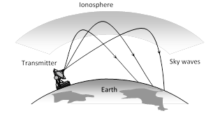 (ii) These are the radio waves of frequency range 2 MHz to 30 MHz.
(iii) Sky waves are used for very long distance radio communication at medium and high frequencies (i.e. at medium waves and short waves).
(iv) The sky waves being electromagnetic in nature, changes the dielectric constant and refractive index of the ionosphere. The effective refractive index of the ionosphere is
\[{{n}_{eff}}={{n}_{0}}{{\left[ 1-\frac{N{{e}^{2}}}{{{\varepsilon }_{0}}m{{\omega }^{2}}} \right]}^{1/2}}={{n}_{0}}{{\left[ 1-\frac{80.5N}{{{f}^{2}}} \right]}^{1/2}}\]
where \[{{n}_{0}}=\] refractive index of free space, N = electron density of ionosphere, \[{{\varepsilon }_{0}}=\] dielectric constant of free space, \[e=\] charge on electron, m = mass of electron \[\omega =\] angular frequency of EM wave.
(v) As we go deep into the ionosphere, N increases so \[{{n}_{eff}}\] decreases. The refractions or bending of the beam will continue and finally it reflects back.
(vi) Critical frequency \[({{f}_{c}})\] : It is defined as the highest frequency of radio wave, which gets reflected to earth by the ionosphere after having been sent straight to it.
If maximum electron density of the ionosphere is \[{{N}_{\max }}\] per \[{{m}^{3}},\] then \[{{f}_{c}}\approx 9{{({{N}_{\max }})}^{1/2}}\]. Above \[{{f}_{c}},\] a wave will penetrate the ionosphere and is not reflected by it.
(vii) Maximum usable frequency (MUF) : It is the highest frequency of radio waves which when sent at some angle of incidence \[\theta \], towards the ionosphere, get reflected and return to the earth. \[MUF=\frac{{{f}_{c}}}{\cos \theta }\]
(viii) Skip distance : It is the more...
(ii) These are the radio waves of frequency range 2 MHz to 30 MHz.
(iii) Sky waves are used for very long distance radio communication at medium and high frequencies (i.e. at medium waves and short waves).
(iv) The sky waves being electromagnetic in nature, changes the dielectric constant and refractive index of the ionosphere. The effective refractive index of the ionosphere is
\[{{n}_{eff}}={{n}_{0}}{{\left[ 1-\frac{N{{e}^{2}}}{{{\varepsilon }_{0}}m{{\omega }^{2}}} \right]}^{1/2}}={{n}_{0}}{{\left[ 1-\frac{80.5N}{{{f}^{2}}} \right]}^{1/2}}\]
where \[{{n}_{0}}=\] refractive index of free space, N = electron density of ionosphere, \[{{\varepsilon }_{0}}=\] dielectric constant of free space, \[e=\] charge on electron, m = mass of electron \[\omega =\] angular frequency of EM wave.
(v) As we go deep into the ionosphere, N increases so \[{{n}_{eff}}\] decreases. The refractions or bending of the beam will continue and finally it reflects back.
(vi) Critical frequency \[({{f}_{c}})\] : It is defined as the highest frequency of radio wave, which gets reflected to earth by the ionosphere after having been sent straight to it.
If maximum electron density of the ionosphere is \[{{N}_{\max }}\] per \[{{m}^{3}},\] then \[{{f}_{c}}\approx 9{{({{N}_{\max }})}^{1/2}}\]. Above \[{{f}_{c}},\] a wave will penetrate the ionosphere and is not reflected by it.
(vii) Maximum usable frequency (MUF) : It is the highest frequency of radio waves which when sent at some angle of incidence \[\theta \], towards the ionosphere, get reflected and return to the earth. \[MUF=\frac{{{f}_{c}}}{\cos \theta }\]
(viii) Skip distance : It is the more... 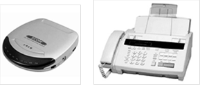 (1) Modem : Modems are used to interface two digital sources/receivers.
(i) Word modem has been obtained from the words modulator and demodulator. As the name implies both the functions (modulation) and demodulation) are included in a signal unit.
(ii) Modems are placed at both ends of the communication circuit as shown.
(1) Modem : Modems are used to interface two digital sources/receivers.
(i) Word modem has been obtained from the words modulator and demodulator. As the name implies both the functions (modulation) and demodulation) are included in a signal unit.
(ii) Modems are placed at both ends of the communication circuit as shown.
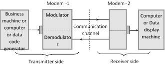 (iii) The modem at the transmitting station changes the digital output from a computer (or any other business machine) to a from (analog signal) which can be easily sent via a communication channel (Telephone line etc.). While the receiving modem reverses the process.
(iv) There are three modes of operation of a modem.
(a) Simplex mode : In this mode data is transmitted in only one direction.
(b) Half duplex : In this mode data is transmitted between the transmitter and the receiver in both direction, but only in one direction at a time.
(c) Full duplex : In this mode, the data are transmitted between the transmitter and receiver in both directions at the same time.
Modem data transmission speed
(iii) The modem at the transmitting station changes the digital output from a computer (or any other business machine) to a from (analog signal) which can be easily sent via a communication channel (Telephone line etc.). While the receiving modem reverses the process.
(iv) There are three modes of operation of a modem.
(a) Simplex mode : In this mode data is transmitted in only one direction.
(b) Half duplex : In this mode data is transmitted between the transmitter and the receiver in both direction, but only in one direction at a time.
(c) Full duplex : In this mode, the data are transmitted between the transmitter and receiver in both directions at the same time.
Modem data transmission speed
| Types | Speed in bits per sec and (bps) |
| Low speed modem | 600 bps |
| Medium speed modem | 600 to 2400 bps |
| High speed modem | 2400 to 10,800 bps |
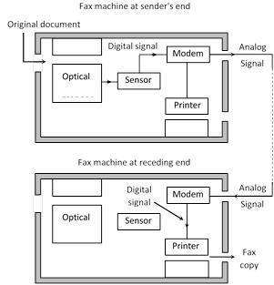 The original written document is put into the machine. A scanner scans the whole document.
The scanned written document is then moved on a glass plate. A beam of light from a given source is projected through the glass and is reflected from the surface of the document.
The original written document is put into the machine. A scanner scans the whole document.
The scanned written document is then moved on a glass plate. A beam of light from a given source is projected through the glass and is reflected from the surface of the document.
 more...
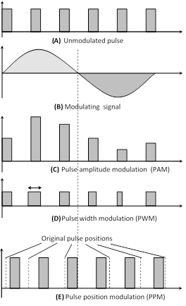
 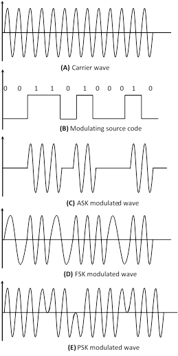 The analog signal is sampled by the sampler. The sampled pulses are then quantised. The encoder codes the quantised pulses according to the binary codes. After modulating the PCM signal (by ASK, FSK or PSK method) the modulated signal is, then transmitted into free space in the form of bits.
| Quantis-ation level | 0 | 1 | 2 | 3 | 4 | 5 | 6 | 7 |
| Binary code | 000 | 001 | 010 |
| Type of broadcast | Frequency band |
| FM radio | 88 to 108 MHz |
| more...
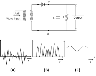
The process of changing the amplitude of a carrier wave in accordance with the amplitude of the audio frequency (AF) signal is known as amplitude modulation (AM).
In AM frequency of the carrier wave remains unchanged.
The amplitude of modulated wave is varied in accordance with the amplitude of modulating wave.
 (1) Modulation index : The ratio of change of amplitude of carrier wave to the amplitude of original carrier wave is called the modulation factor or degree of modulation or modulation index \[({{m}_{a}})\].
\[{{m}_{a}}=\frac{\text{Change in amplitude of carrier wave}}{\text{Amplitude of original carrier wave}}=\frac{k{{E}_{m}}}{{{E}_{c}}}\]
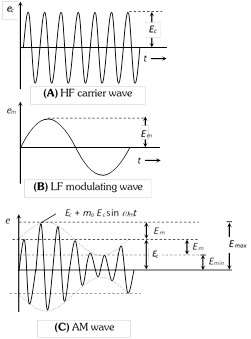
where k = A factor which determines the maximum change in the amplitude for a given amplitude \[{{E}_{m}}\]of the modulating signal. If k = 1 then \[{{m}_{a}}=\frac{{{E}_{m}}}{{{E}_{c}}}=\frac{{{E}_{\max }}-{{E}_{\min }}}{{{E}_{\max }}+{{E}_{\min }}}\]
If a carrier wave is modulated by several sine waves the total modulated index \[{{m}_{t}}\] is given by \[{{m}_{t}}=\sqrt{m_{1}^{2}+m_{2}^{2}+m_{3}^{2}+........}\]
(2) Voltage equation for AM wave : Suppose voltage equations for carrier wave and modulating wave are \[{{e}_{c}}={{E}_{c}}\cos {{\omega }_{c}}t\] and \[{{e}_{m}}={{E}_{m}}\sin {{\omega }_{m}}t=m{{E}_{c}}\sin {{\omega }_{m}}t\]
where \[{{e}_{c}}=\] Instantaneous voltage of carrier wave, \[{{E}_{c}}=\] Amplitude of carrier wave, \[{{\omega }_{c}}=2\pi \,{{f}_{c}}=\] Angular velocity at carrier frequency \[{{f}_{c}}\], \[{{e}_{m}}=\] Instantaneous voltage of modulating, \[{{E}_{m}}=\] Amplitude of modulating wave, \[{{\omega }_{m}}=2\pi \,{{f}_{m}}=\]Angular velocity of modulating frequency \[{{f}_{m}}\]
Voltage equation for AM wave is
\[e=E\sin {{\omega }_{c}}t=({{E}_{c}}+{{e}_{m}})\sin {{\omega }_{c}}t\]\[=({{E}_{c}}+{{e}_{m}}\sin {{\omega }_{m}}t)\sin {{\omega }_{c}}t\] \[={{E}_{c}}\sin {{\omega }_{c}}t+\frac{{{m}_{a}}{{E}_{c}}}{2}\cos ({{\omega }_{c}}-{{\omega }_{m}})t-\frac{{{m}_{a}}{{E}_{c}}}{2}\cos \,({{\omega }_{c}}+{{\omega }_{m}})t\]
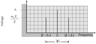
The above AM wave indicated that the AM wave is equivalent to summation of three sinusoidal wave, one having amplitude \[{{E}_{c}}\]and the other two having amplitude \[\frac{{{m}_{a}}{{E}_{c}}}{2}\].
(3) Side band frequencies and band width in AM wave
(i) Side band frequencies : The AM wave contains three frequencies \[{{f}_{c}},\,({{f}_{c}}+{{f}_{m}})\] and \[({{f}_{c}}-{{f}_{m}}),\] \[{{f}_{c}}\] is called carrier frequency, \[({{f}_{c}}+{{f}_{m}})\] and \[({{f}_{c}}-{{f}_{m}})\] are called side band frequencies.
\[({{f}_{c}}+{{f}_{m}}):\] Upper side band (USB) frequency
\[({{f}_{c}}-{{f}_{m}}):\] Lower side band (LSB) frequency
Side band frequencies are generally close to the carrier frequency.
(ii) Band width : The two side bands lie on either side of the carrier frequency at equal frequency interval \[{{f}_{m}}\]. So, band width \[=({{f}_{c}}+{{f}_{m}})-\,({{f}_{c}}-{{f}_{m}})=2{{f}_{m}}\]
(1) Modulation index : The ratio of change of amplitude of carrier wave to the amplitude of original carrier wave is called the modulation factor or degree of modulation or modulation index \[({{m}_{a}})\].
\[{{m}_{a}}=\frac{\text{Change in amplitude of carrier wave}}{\text{Amplitude of original carrier wave}}=\frac{k{{E}_{m}}}{{{E}_{c}}}\]
where k = A factor which determines the maximum change in the amplitude for a given amplitude \[{{E}_{m}}\]of the modulating signal. If k = 1 then \[{{m}_{a}}=\frac{{{E}_{m}}}{{{E}_{c}}}=\frac{{{E}_{\max }}-{{E}_{\min }}}{{{E}_{\max }}+{{E}_{\min }}}\]
If a carrier wave is modulated by several sine waves the total modulated index \[{{m}_{t}}\] is given by \[{{m}_{t}}=\sqrt{m_{1}^{2}+m_{2}^{2}+m_{3}^{2}+........}\]
(2) Voltage equation for AM wave : Suppose voltage equations for carrier wave and modulating wave are \[{{e}_{c}}={{E}_{c}}\cos {{\omega }_{c}}t\] and \[{{e}_{m}}={{E}_{m}}\sin {{\omega }_{m}}t=m{{E}_{c}}\sin {{\omega }_{m}}t\]
where \[{{e}_{c}}=\] Instantaneous voltage of carrier wave, \[{{E}_{c}}=\] Amplitude of carrier wave, \[{{\omega }_{c}}=2\pi \,{{f}_{c}}=\] Angular velocity at carrier frequency \[{{f}_{c}}\], \[{{e}_{m}}=\] Instantaneous voltage of modulating, \[{{E}_{m}}=\] Amplitude of modulating wave, \[{{\omega }_{m}}=2\pi \,{{f}_{m}}=\]Angular velocity of modulating frequency \[{{f}_{m}}\]
Voltage equation for AM wave is
\[e=E\sin {{\omega }_{c}}t=({{E}_{c}}+{{e}_{m}})\sin {{\omega }_{c}}t\]\[=({{E}_{c}}+{{e}_{m}}\sin {{\omega }_{m}}t)\sin {{\omega }_{c}}t\] \[={{E}_{c}}\sin {{\omega }_{c}}t+\frac{{{m}_{a}}{{E}_{c}}}{2}\cos ({{\omega }_{c}}-{{\omega }_{m}})t-\frac{{{m}_{a}}{{E}_{c}}}{2}\cos \,({{\omega }_{c}}+{{\omega }_{m}})t\]
The above AM wave indicated that the AM wave is equivalent to summation of three sinusoidal wave, one having amplitude \[{{E}_{c}}\]and the other two having amplitude \[\frac{{{m}_{a}}{{E}_{c}}}{2}\].
(3) Side band frequencies and band width in AM wave
(i) Side band frequencies : The AM wave contains three frequencies \[{{f}_{c}},\,({{f}_{c}}+{{f}_{m}})\] and \[({{f}_{c}}-{{f}_{m}}),\] \[{{f}_{c}}\] is called carrier frequency, \[({{f}_{c}}+{{f}_{m}})\] and \[({{f}_{c}}-{{f}_{m}})\] are called side band frequencies.
\[({{f}_{c}}+{{f}_{m}}):\] Upper side band (USB) frequency
\[({{f}_{c}}-{{f}_{m}}):\] Lower side band (LSB) frequency
Side band frequencies are generally close to the carrier frequency.
(ii) Band width : The two side bands lie on either side of the carrier frequency at equal frequency interval \[{{f}_{m}}\]. So, band width \[=({{f}_{c}}+{{f}_{m}})-\,({{f}_{c}}-{{f}_{m}})=2{{f}_{m}}\]
 (4) Power in AM waves : Power dissipated in any circuit \[P=\frac{V_{rms}^{2}}{R}\]. Hence (i) carrier power \[{{P}_{c}}=\frac{{{\left( \frac{{{E}_{c}}}{\sqrt{2}} \right)}^{2}}}{R}=\frac{E_{c}^{2}}{2R}\]
(ii) Total power of side bands \[{{P}_{sb}}=\frac{{{\left( \frac{{{m}_{a}}{{E}_{c}}}{2\sqrt{2}} \right)}^{2}}}{R}+\frac{\left( \frac{{{m}_{a}}{{E}_{c}}}{2\sqrt{2}} \right)}{R}\]\[=\frac{m_{a}^{2}E_{c}^{2}}{4R}\]
(iii) Total power of AM wave \[{{P}_{Total}}={{P}_{c}}+{{P}_{sb}}\]\[=\frac{E_{c}^{2}}{2R}\left( 1+\frac{m_{a}^{2}}{2} \right)\]
(iv) \[\frac{{{P}_{t}}}{{{P}_{c}}}=\left( 1+\frac{m_{a}^{2}}{2} \right)\] and \[\frac{{{P}_{sb}}}{{{P}_{t}}}=\frac{m_{a}^{2}/2}{\left( 1+\frac{m_{a}^{2}}{2} \right)}\]
(v) Maximum power in the AM (without distortion) will occur when \[{{m}_{a}}=1\] i.e. \[{{P}_{t}}=1.5P=3{{P}_{sb}}\]
(vi) If \[{{l}_{c}}=\] Unmodulated current and \[{{l}_{t}}=\] total or modulated current \[\Rightarrow \]\[\frac{{{P}_{t}}}{{{P}_{c}}}=\frac{I_{t}^{2}}{I_{c}^{2}}\]\[\Rightarrow \]\[\frac{{{I}_{t}}}{{{I}_{c}}}=\sqrt{\left( 1+\frac{m_{a}^{2}}{2} \right)}\]
(5) Limitation of amplitude modulation
(i) Noisy reception
(ii) Low efficiency
(iii) Small operating range
(iv) Poor audio quality
(4) Power in AM waves : Power dissipated in any circuit \[P=\frac{V_{rms}^{2}}{R}\]. Hence (i) carrier power \[{{P}_{c}}=\frac{{{\left( \frac{{{E}_{c}}}{\sqrt{2}} \right)}^{2}}}{R}=\frac{E_{c}^{2}}{2R}\]
(ii) Total power of side bands \[{{P}_{sb}}=\frac{{{\left( \frac{{{m}_{a}}{{E}_{c}}}{2\sqrt{2}} \right)}^{2}}}{R}+\frac{\left( \frac{{{m}_{a}}{{E}_{c}}}{2\sqrt{2}} \right)}{R}\]\[=\frac{m_{a}^{2}E_{c}^{2}}{4R}\]
(iii) Total power of AM wave \[{{P}_{Total}}={{P}_{c}}+{{P}_{sb}}\]\[=\frac{E_{c}^{2}}{2R}\left( 1+\frac{m_{a}^{2}}{2} \right)\]
(iv) \[\frac{{{P}_{t}}}{{{P}_{c}}}=\left( 1+\frac{m_{a}^{2}}{2} \right)\] and \[\frac{{{P}_{sb}}}{{{P}_{t}}}=\frac{m_{a}^{2}/2}{\left( 1+\frac{m_{a}^{2}}{2} \right)}\]
(v) Maximum power in the AM (without distortion) will occur when \[{{m}_{a}}=1\] i.e. \[{{P}_{t}}=1.5P=3{{P}_{sb}}\]
(vi) If \[{{l}_{c}}=\] Unmodulated current and \[{{l}_{t}}=\] total or modulated current \[\Rightarrow \]\[\frac{{{P}_{t}}}{{{P}_{c}}}=\frac{I_{t}^{2}}{I_{c}^{2}}\]\[\Rightarrow \]\[\frac{{{I}_{t}}}{{{I}_{c}}}=\sqrt{\left( 1+\frac{m_{a}^{2}}{2} \right)}\]
(5) Limitation of amplitude modulation
(i) Noisy reception
(ii) Low efficiency
(iii) Small operating range
(iv) Poor audio quality
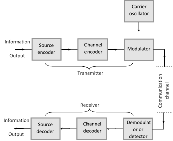
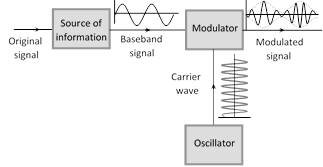
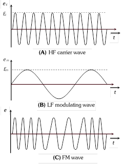
(1) Digital and analog signals to be transmitted are usually of low frequency and hence cannot be transmitted as such.
(2) These signals require some carrier to be transported. These carriers are known as carrier waves or high frequency signals.
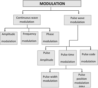
(3) The process of placement of a low frequency (LF) signal over the high frequency (HF) signal is known as modulation.
 (4) Need for modulation : The sound wave (20 Hz to 20 KHz) cannot be transmitted directly from one place to another for the following reasons.
(i) Height of anteena : For efficient radiation and reception , the height of transmitting and receiving antennas should be comparable to a quarter of wavelength of the frequency used. For 15 KHz it is 5000 m (too large) and for 1 MHz it is 75 m.
The energy radiated from an anteena is practically zero, when the frequency of the signal to be transmitted is below 15 Hz.
(ii) Detecting signals : All audible signals are in the range of 20 Hz to 20 KHz so the signals from all sources remains heavily mixed up in air. It will be very difficult to differentiate or detect the broadcast signal at the receiving station.
Thus modulation is necessary for a low frequency signal. When it is to be sent to a distant place so that the information may not die out in the way it self as well as for the proper identification of a signal and to keep the height of anteena small also
(4) Need for modulation : The sound wave (20 Hz to 20 KHz) cannot be transmitted directly from one place to another for the following reasons.
(i) Height of anteena : For efficient radiation and reception , the height of transmitting and receiving antennas should be comparable to a quarter of wavelength of the frequency used. For 15 KHz it is 5000 m (too large) and for 1 MHz it is 75 m.
The energy radiated from an anteena is practically zero, when the frequency of the signal to be transmitted is below 15 Hz.
(ii) Detecting signals : All audible signals are in the range of 20 Hz to 20 KHz so the signals from all sources remains heavily mixed up in air. It will be very difficult to differentiate or detect the broadcast signal at the receiving station.
Thus modulation is necessary for a low frequency signal. When it is to be sent to a distant place so that the information may not die out in the way it self as well as for the proper identification of a signal and to keep the height of anteena small also
In communication system, a signal means a time varying electrical signal containing informations.
(1) Analog signals : It is a continuous wave form which changes smoothly over time.
(i) Such signals can be easily generated from the source of information by using an appropriate transducer e.g. pressure variations in the sound waves can be converted into corresponding current or voltage pulses with the help of a microphone.
(ii) A simple analog signal is represented by a sine wave
 (iii) The frequency of analog signals associated with speed or music varies over a range between 20 Hz to 20 KHz. (iv) The range over which the frequencies of a signal vary is called band width.
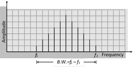 (v) The term base band designates the band of frequencies representing the signal supplied by the source of information.
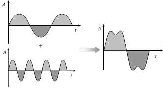
(vi) A signal consist of two or more waves of different frequencies is known as a complex analog signal.
(v) The term base band designates the band of frequencies representing the signal supplied by the source of information.
(vi) A signal consist of two or more waves of different frequencies is known as a complex analog signal.
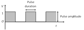
 (2) Digital signals : A digital signal is a discontinuous function of time. It has only two voltage level i.e. either low (0) or high (1).
Either of 0 and 1 is known as bit. A group of bit is called byte. A byte comprising of 2 bits can give on the four code combination i.e. 00, 01, 10 and 11.
The number of code combination increase with number of bits in a byte is given by \[N={{2}^{x}}\], where x = number of bits in a byte.
The number of binary digits (bits) per second, which describe a digital signal is called it's bit rate. Bit rate is expressed in bits per second (bps).
(2) Digital signals : A digital signal is a discontinuous function of time. It has only two voltage level i.e. either low (0) or high (1).
Either of 0 and 1 is known as bit. A group of bit is called byte. A byte comprising of 2 bits can give on the four code combination i.e. 00, 01, 10 and 11.
The number of code combination increase with number of bits in a byte is given by \[N={{2}^{x}}\], where x = number of bits in a byte.
The number of binary digits (bits) per second, which describe a digital signal is called it's bit rate. Bit rate is expressed in bits per second (bps).
 Current Affairs CategoriesArchive
Trending Current Affairs


You need to login to perform this action. |


 (4) Frequency deviation : The maximum change in frequency from mean value \[({{v}_{c}})\] is known as frequency deviation. This is also the change or shift either above or below the frequency \[{{v}_{c}}\] and is called as frequency deviation.
\[\therefore \] \[\delta =({{f}_{\max }}-{{f}_{c}})={{f}_{c}}-{{f}_{\min }}={{k}_{f}}.\frac{{{E}_{m}}}{2\pi }\]
\[{{k}_{f}}=\] Constant of proportionality. It determines the maximum variation in frequency of the modulated wave for a given modulating signal.
(5) Carrier swing (CS) : The total variation in frequency from the lowest to the highest is called the carrier swing i.e.
\[CS=2\times \Delta f\]
(6) Frequency modulation index \[({{m}_{f}})\] : The ratio of maximum frequency deviation to the modulating frequency is called modulation index.
\[{{m}_{f}}=\frac{\delta }{{{f}_{m}}}=\frac{{{f}_{\max }}-{{f}_{c}}}{{{f}_{m}}}=\frac{{{f}_{c}}-{{f}_{\min }}}{{{f}_{m}}}=\frac{{{k}_{f}}{{E}_{m}}}{{{f}_{m}}}\]
(7) Frequency spectrum : FM side band modulated signal consist of infinite number of side bands whose frequencies are
\[({{f}_{c}}\pm {{f}_{m}}),\,({{f}_{c}}\pm 2{{f}_{m}}),\,({{f}_{c}}\pm 3{{f}_{m}})\,.......\]
The number of side bands depends on the modulation index \[{{m}_{f}}\].
(4) Frequency deviation : The maximum change in frequency from mean value \[({{v}_{c}})\] is known as frequency deviation. This is also the change or shift either above or below the frequency \[{{v}_{c}}\] and is called as frequency deviation.
\[\therefore \] \[\delta =({{f}_{\max }}-{{f}_{c}})={{f}_{c}}-{{f}_{\min }}={{k}_{f}}.\frac{{{E}_{m}}}{2\pi }\]
\[{{k}_{f}}=\] Constant of proportionality. It determines the maximum variation in frequency of the modulated wave for a given modulating signal.
(5) Carrier swing (CS) : The total variation in frequency from the lowest to the highest is called the carrier swing i.e.
\[CS=2\times \Delta f\]
(6) Frequency modulation index \[({{m}_{f}})\] : The ratio of maximum frequency deviation to the modulating frequency is called modulation index.
\[{{m}_{f}}=\frac{\delta }{{{f}_{m}}}=\frac{{{f}_{\max }}-{{f}_{c}}}{{{f}_{m}}}=\frac{{{f}_{c}}-{{f}_{\min }}}{{{f}_{m}}}=\frac{{{k}_{f}}{{E}_{m}}}{{{f}_{m}}}\]
(7) Frequency spectrum : FM side band modulated signal consist of infinite number of side bands whose frequencies are
\[({{f}_{c}}\pm {{f}_{m}}),\,({{f}_{c}}\pm 2{{f}_{m}}),\,({{f}_{c}}\pm 3{{f}_{m}})\,.......\]
The number of side bands depends on the modulation index \[{{m}_{f}}\].
 In FM signal, the information (audio signal) is contained in the side bands. Since the side bands are separated from each other by the frequency of modulating signal \[{{f}_{m}}\]so
Band width \[=2n\times {{f}_{m}}\]; where n = number of significant side band pairs
(8) Deviation ratio : The ratio of maximum permitted frequency deviation to the maximum permitted audio frequency is known as deviation ratio. Thus, deviation ratio \[=\frac{{{(\Delta f)}_{\max }}}{{{({{f}_{m}})}_{\max }}}\]
(9) Percent modulation : The ratio of actual frequency deviation to the maximum allowed frequency deviation is defined as percent modulation. Thus, percent modulation, \[m=\frac{{{(\Delta f)}_{\text{actual}}}}{{{(\Delta f)}_{\max }}}\]
Range of frequency allotted for FM radio/TV broadcast
In FM signal, the information (audio signal) is contained in the side bands. Since the side bands are separated from each other by the frequency of modulating signal \[{{f}_{m}}\]so
Band width \[=2n\times {{f}_{m}}\]; where n = number of significant side band pairs
(8) Deviation ratio : The ratio of maximum permitted frequency deviation to the maximum permitted audio frequency is known as deviation ratio. Thus, deviation ratio \[=\frac{{{(\Delta f)}_{\max }}}{{{({{f}_{m}})}_{\max }}}\]
(9) Percent modulation : The ratio of actual frequency deviation to the maximum allowed frequency deviation is defined as percent modulation. Thus, percent modulation, \[m=\frac{{{(\Delta f)}_{\text{actual}}}}{{{(\Delta f)}_{\max }}}\]
Range of frequency allotted for FM radio/TV broadcast