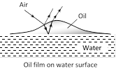
 In thin films interference takes place between the waves reflected from it?s two surfaces and waves refracted through it.
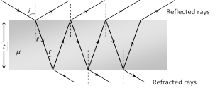 (1) Interference in reflected light : Condition of constructive interference (maximum intensity)
\[\Delta =2\mu \,\,t\cos r=(2n-1)\frac{\lambda }{2}\]. For normal incidence r = 0 so \[2\mu \,t=(2n-1)\,_{2}^{\lambda }\]
Condition of destructive interference (minimum intensity)
\[\Delta =2\mu \,t\,\cos r=(2n)\frac{\lambda }{2}\].
For normal incidence \[2\mu \,t=n\lambda \]
(2) Interference in refracted light : Condition of constructive interference (maximum intensity)
\[\Delta =2\mu \,t\,\cos r=(2n)\frac{\lambda }{2}\]. For normal incidence \[2\mu \,t=n\lambda \]
Condition of destructive interference (minimum intensity)
\[\Delta =2\mu \,t\,\cos r=(2n-1)\frac{\lambda }{2}\]
For normal incidence \[2\mu \,t=(2n-1)\frac{\lambda }{2}\]
(1) Interference in reflected light : Condition of constructive interference (maximum intensity)
\[\Delta =2\mu \,\,t\cos r=(2n-1)\frac{\lambda }{2}\]. For normal incidence r = 0 so \[2\mu \,t=(2n-1)\,_{2}^{\lambda }\]
Condition of destructive interference (minimum intensity)
\[\Delta =2\mu \,t\,\cos r=(2n)\frac{\lambda }{2}\].
For normal incidence \[2\mu \,t=n\lambda \]
(2) Interference in refracted light : Condition of constructive interference (maximum intensity)
\[\Delta =2\mu \,t\,\cos r=(2n)\frac{\lambda }{2}\]. For normal incidence \[2\mu \,t=n\lambda \]
Condition of destructive interference (minimum intensity)
\[\Delta =2\mu \,t\,\cos r=(2n-1)\frac{\lambda }{2}\]
For normal incidence \[2\mu \,t=(2n-1)\frac{\lambda }{2}\] 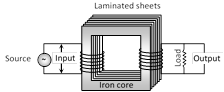 (1) Transformer works on ac only and never on dc.
(2) It can increase or decrease either voltage or current but not both simultaneously.
(3) Transformer does not change the frequency of input ac.
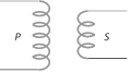
(4) There is no electrical connection between the winding but they are linked magnetically.
(5) Effective resistance between primary and secondary winding is infinite.
(6) The flux per turn of each coil must be same i.e. \[{{\varphi }_{S}}={{\varphi }_{P}}\]; \[-\frac{d{{\varphi }_{S}}}{dt}=-\frac{d{{\varphi }_{P}}}{dt}\].
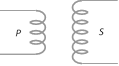
(7) If \[{{N}_{P}}=\] number of turns in primary, \[{{N}_{S}}=\] number of turns in secondary, \[{{V}_{P}}=\] applied (input) voltage to primary, \[{{V}_{S}}=\] Voltage across secondary (load voltage or output), \[{{e}_{P}}=\] induced emf in primary ; \[{{e}_{S}}=\]induced emf in secondary, \[\phi =\] flux linked with primary as well as secondary, current in primary; \[{{i}_{S}}=\]current in secondary (or load current)
As in an ideal transformer there is no loss of power i.e.\[{{P}_{out}}={{P}_{in}}\]so \[{{V}_{S}}{{i}_{S}}={{V}_{P}}{{i}_{P}}\] and \[{{V}_{P}}\approx {{e}_{P}}\], \[{{V}_{S}}\approx {{e}_{S}}\]. Hence \[\frac{{{e}_{S}}}{{{e}_{P}}}=\frac{{{N}_{S}}}{{{N}_{P}}}=\frac{{{V}_{S}}}{{{V}_{P}}}=\frac{{{i}_{P}}}{{{i}_{S}}}=k\]; k = Transformation ratio (or turn ratio)
Types of transformer
(1) Transformer works on ac only and never on dc.
(2) It can increase or decrease either voltage or current but not both simultaneously.
(3) Transformer does not change the frequency of input ac.
(4) There is no electrical connection between the winding but they are linked magnetically.
(5) Effective resistance between primary and secondary winding is infinite.
(6) The flux per turn of each coil must be same i.e. \[{{\varphi }_{S}}={{\varphi }_{P}}\]; \[-\frac{d{{\varphi }_{S}}}{dt}=-\frac{d{{\varphi }_{P}}}{dt}\].
(7) If \[{{N}_{P}}=\] number of turns in primary, \[{{N}_{S}}=\] number of turns in secondary, \[{{V}_{P}}=\] applied (input) voltage to primary, \[{{V}_{S}}=\] Voltage across secondary (load voltage or output), \[{{e}_{P}}=\] induced emf in primary ; \[{{e}_{S}}=\]induced emf in secondary, \[\phi =\] flux linked with primary as well as secondary, current in primary; \[{{i}_{S}}=\]current in secondary (or load current)
As in an ideal transformer there is no loss of power i.e.\[{{P}_{out}}={{P}_{in}}\]so \[{{V}_{S}}{{i}_{S}}={{V}_{P}}{{i}_{P}}\] and \[{{V}_{P}}\approx {{e}_{P}}\], \[{{V}_{S}}\approx {{e}_{S}}\]. Hence \[\frac{{{e}_{S}}}{{{e}_{P}}}=\frac{{{N}_{S}}}{{{N}_{P}}}=\frac{{{V}_{S}}}{{{V}_{P}}}=\frac{{{i}_{P}}}{{{i}_{S}}}=k\]; k = Transformation ratio (or turn ratio)
Types of transformer
| Step up transformer | Step down transformer |
It increases voltage and decreases current
|
It decreases voltage and increases current
|
| \[{{V}_{S}}>{{V}_{P}}\] | \[{{V}_{S}}<{{V}_{P}}\] |
| \[{{N}_{S}}>{{N}_{P}}\] | \[{{N}_{S}}<{{N}_{P}}\] |
| \[{{E}_{S}}>{{E}_{P}}~\] | \[{{E}_{S}}<{{E}_{P}}~\] |
| \[{{i}_{S}}<{{i}_{P}}\] | more...
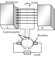
If the current produced by the generator is direct current, then the generator is called dc generator.
dc generator consists of (i) Armature (coil) (ii) Magnet (iii) Commutator (iv) Brushes
In dc generator commutator is used in place of slip rings. The commutator rotates along with the coil so that in every cycle when direction of \['e'\] reverses, the commutator also reverses or makes contact with the other brush so that in the external load the current remains in the some direction giving dc
Suppose P is a point of observation infront of slit \[{{S}_{1}}\] as shown
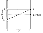 Missing wavelength at P
\[\lambda =\frac{{{d}^{\mathbf{2}}}}{\mathbf{(2}n-\mathbf{1)}D}\]
By putting \[n=1,\,2,\,3\,....\] Missing wavelengths are
\[\lambda =\frac{{{d}^{2}}}{D},\,\frac{{{d}^{2}}}{3D},\,\frac{{{d}^{2}}}{5D}....\]
Missing wavelength at P
\[\lambda =\frac{{{d}^{\mathbf{2}}}}{\mathbf{(2}n-\mathbf{1)}D}\]
By putting \[n=1,\,2,\,3\,....\] Missing wavelengths are
\[\lambda =\frac{{{d}^{2}}}{D},\,\frac{{{d}^{2}}}{3D},\,\frac{{{d}^{2}}}{5D}....\]
An electrical machine used to convert mechanical energy into electrical energy is known as ac generator/alternator.
(1) Principle : It works on the principle of electromagnetic induction i.e., when a coil is rotated in uniform magnetic field, an induced emf is produced in it.
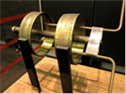
(2) Construction : The main components of ac generator are
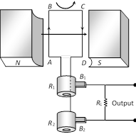 (i) Armature : Armature coil (ABCD) consists of large number of turns of insulated copper wire wound over a soft iron core.
(ii) Strong field magnet : A strong permanent magnet or an electromagnet whose poles (N and S) are cylindrical in shape in a field magnet. The armature coil rotates between the pole pieces of the field magnet. The uniform magnetic field provided by the field magnet is perpendicular to the axis of rotation of the coil.
(iii) Slip rings : The two ends of the armature coil are connected to two brass slip rings R1 and R2 . These rings rotate along with the armature coil.
(iv) Brushes : Two carbon brushes (\[{{B}_{1}}\] and \[{{B}_{2}}\]), are pressed against the slip rings. The brushes are fixed while slip rings rotate along with the armature. These brushes are connected to the load through which the output is obtained.
(3) Working : When the armature coil ABCD rotates in the magnetic field provided by the strong field magnet, it cuts the magnetic lines of force. Thus the magnetic flux linked with the coil changes and hence induced emf is set up in the coil. The direction of the induced emf or the current in the coil is determined by the Fleming's right hand rule.
The current flows out through the brush \[{{B}_{1}}\] in one direction of half of the revolution and through the brush \[{{B}_{2}}\] in the next half revolution in the reverse direction. This process is repeated. Therefore, emf produced is of alternating nature.
\[e=-\frac{Nd\varphi }{dt}=NBA\omega \sin \omega t={{e}_{0}}\sin \omega t\] where \[{{e}_{0}}=NBA\omega \]
\[i=\frac{e}{R}=\frac{{{e}_{0}}}{R}\sin \omega t={{i}_{0}}\sin \omega t\]\[R\to R\] Resistance of the circuit
(i) Armature : Armature coil (ABCD) consists of large number of turns of insulated copper wire wound over a soft iron core.
(ii) Strong field magnet : A strong permanent magnet or an electromagnet whose poles (N and S) are cylindrical in shape in a field magnet. The armature coil rotates between the pole pieces of the field magnet. The uniform magnetic field provided by the field magnet is perpendicular to the axis of rotation of the coil.
(iii) Slip rings : The two ends of the armature coil are connected to two brass slip rings R1 and R2 . These rings rotate along with the armature coil.
(iv) Brushes : Two carbon brushes (\[{{B}_{1}}\] and \[{{B}_{2}}\]), are pressed against the slip rings. The brushes are fixed while slip rings rotate along with the armature. These brushes are connected to the load through which the output is obtained.
(3) Working : When the armature coil ABCD rotates in the magnetic field provided by the strong field magnet, it cuts the magnetic lines of force. Thus the magnetic flux linked with the coil changes and hence induced emf is set up in the coil. The direction of the induced emf or the current in the coil is determined by the Fleming's right hand rule.
The current flows out through the brush \[{{B}_{1}}\] in one direction of half of the revolution and through the brush \[{{B}_{2}}\] in the next half revolution in the reverse direction. This process is repeated. Therefore, emf produced is of alternating nature.
\[e=-\frac{Nd\varphi }{dt}=NBA\omega \sin \omega t={{e}_{0}}\sin \omega t\] where \[{{e}_{0}}=NBA\omega \]
\[i=\frac{e}{R}=\frac{{{e}_{0}}}{R}\sin \omega t={{i}_{0}}\sin \omega t\]\[R\to R\] Resistance of the circuit
It is an electrical machine which converts electrical energy into mechanical energy.
 (1) Principle : It is based on the fact that a current carrying coil placed in the magnetic field experiences a torque. This torque rotates the coil.
(2) Construction : It consists of the following components figure..
(1) Principle : It is based on the fact that a current carrying coil placed in the magnetic field experiences a torque. This torque rotates the coil.
(2) Construction : It consists of the following components figure..
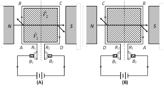 ABCD = Armature coil, \[{{S}_{1}},\,{{S}_{2}}=\]split ring comutators
\[{{B}_{1}},\,\,{{B}_{2}}=\] Carbon brushes, N, S = Strong magnetic poles
(3) Working : Force on any arm of the coil is given by \[\vec{F}=i(\vec{l}\times \vec{B})\] in fig., force on AB will be perpendicular to plane of the paper and pointing inwards. Force on CD will be equal and opposite. So coil rotates in clockwise sense when viewed from top in fig. The current in AB reverses due to commutation keeping the force on AB and CD in such a direction that the coil continues to rotate in the same direction.
(4) Back emf in motor : Due to the rotation of armature coil in magnetic field a back emf is induced in the circuit. Which is given by \[e=E-iR\].
Back emf directly depends upon the angular velocity \[\omega \]of armature and magnetic field B. But for constant magnetic field B, value of back emf e is given by \[e\propto \omega \] or \[e=k\omega \]\[(e=NBA\,\omega \sin \omega t)\]
(5) Current in the motor : \[i=\frac{E-e}{R}=\frac{E-k\omega }{R}\]; When motor is just switched on i.e. \[\omega =0\] so \[e=0\] hence \[i=\frac{E}{R}=\text{maximum}\] and at full speed, \[\omega \] is maximum so back emf e is maximum and i is minimum. Thus, maximum current is drawn when the motor is just switched on which decreases when motor attains the speed.
(6) Motor starter : At the time of start a large current flows through the motor which may burn out it. Hence a starter is used for starting a dc motor safely. Its function is to introduce a suitable resistance in the circuit at the time of starting of the motor. This resistance decreases gradually and reduces to zero when the motor runs at full sped.
ABCD = Armature coil, \[{{S}_{1}},\,{{S}_{2}}=\]split ring comutators
\[{{B}_{1}},\,\,{{B}_{2}}=\] Carbon brushes, N, S = Strong magnetic poles
(3) Working : Force on any arm of the coil is given by \[\vec{F}=i(\vec{l}\times \vec{B})\] in fig., force on AB will be perpendicular to plane of the paper and pointing inwards. Force on CD will be equal and opposite. So coil rotates in clockwise sense when viewed from top in fig. The current in AB reverses due to commutation keeping the force on AB and CD in such a direction that the coil continues to rotate in the same direction.
(4) Back emf in motor : Due to the rotation of armature coil in magnetic field a back emf is induced in the circuit. Which is given by \[e=E-iR\].
Back emf directly depends upon the angular velocity \[\omega \]of armature and magnetic field B. But for constant magnetic field B, value of back emf e is given by \[e\propto \omega \] or \[e=k\omega \]\[(e=NBA\,\omega \sin \omega t)\]
(5) Current in the motor : \[i=\frac{E-e}{R}=\frac{E-k\omega }{R}\]; When motor is just switched on i.e. \[\omega =0\] so \[e=0\] hence \[i=\frac{E}{R}=\text{maximum}\] and at full speed, \[\omega \] is maximum so back emf e is maximum and i is minimum. Thus, maximum current is drawn when the motor is just switched on which decreases when motor attains the speed.
(6) Motor starter : At the time of start a large current flows through the motor which may burn out it. Hence a starter is used for starting a dc motor safely. Its function is to introduce a suitable resistance in the circuit at the time of starting of the motor. This resistance decreases gradually and reduces to zero when the motor runs at full sped.
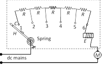 The value of starting resistance is maximum at time \[t=0\] and its value is controlled by spring and electromagnetic system and is made to zero when the motor attains its safe speed.
(7) Mechanical power and Efficiency of dc motor :
Efficiency \[\eta =\frac{{{P}_{mechanical}}}{{{P}_{\sup plied}}}=\frac{{{P}_{out}}}{{{P}_{in}}}\]\[=\frac{e}{E}=\frac{\text{Back e}\text{.m}\text{.f}\text{.}}{\text{Supply voltage}}\]
(8) Uses of dc motors : They are used in electric locomotives, electric ears, rolling mills, electric cranes, electric lifts, dc drills, fans and blowers, centrifugal pumps and air compressors, etc.
The value of starting resistance is maximum at time \[t=0\] and its value is controlled by spring and electromagnetic system and is made to zero when the motor attains its safe speed.
(7) Mechanical power and Efficiency of dc motor :
Efficiency \[\eta =\frac{{{P}_{mechanical}}}{{{P}_{\sup plied}}}=\frac{{{P}_{out}}}{{{P}_{in}}}\]\[=\frac{e}{E}=\frac{\text{Back e}\text{.m}\text{.f}\text{.}}{\text{Supply voltage}}\]
(8) Uses of dc motors : They are used in electric locomotives, electric ears, rolling mills, electric cranes, electric lifts, dc drills, fans and blowers, centrifugal pumps and air compressors, etc.
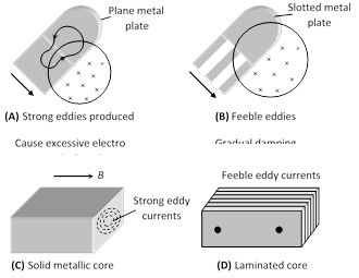
When a changing magnetic flux is applied to a bulk piece of conducting material then circulating currents called eddy currents are induced in the material. Because the resistance of the bulk conductor is usually low, eddy currents often have large magnitudes and heat up the conductor.
(1) These are circulating currents like eddies in water.
(2) Experimental concept given by Focault hence also named as 'Focault current'.
(3) The production of eddy currents in a metallic block leads to the loss of electric energy in the form of heat.
(4) By Lamination, slotting processes the resistance path for circulation of eddy current increases, resulting in to weakening them and also reducing losses causes by them
 (5) Application of eddy currents : Though most of the times eddy currents are undesirable but they find some useful applications as enumerated below
(i) Dead-beat galvanometer : A dead beat galvanometer means one whose pointer comes to rest in the final equilibrium position immediately without any oscillation about the equilibrium position when a current is passed in its coil.
This is achieved by winding the coil on a metallic frame the large eddy currents induced in the frame provide electromagnetic damping.
(ii) Electric-brakes : When the train is running its wheel is moving in air and when the train is to be stopped by electric breaks the wheel is made to move in a field created by electromagnet. Eddy currents induced in the wheels due to the changing flux oppose the cause and stop the train.
(iii) Induction furnace : Joule's heat causes the melting of a metal piece placed in a rapidly changing magnetic field.
(iv) Speedometer : In the speedometer of an automobile, a magnet is geared to the main shaft of the vehicle and it rotates according to the speed of the vehicle. The magnet is mounted in an aluminium cylinder with the help of hair springs. When the magnet rotates, it produces eddy currents in the drum and drags it through an angle, which indicates the speed of the vehicle on a calibrated scale.
(v) Energy meter : In energy meters, the armature coil carries a metallic aluminium disc which rotates between the poles of a pair of permanent horse shoe magnets. As the armature rotates, the current induced in the disc tends to oppose the motion of the armature coil. Due to this braking effect, deflection is proportional to the energy consumed.
(5) Application of eddy currents : Though most of the times eddy currents are undesirable but they find some useful applications as enumerated below
(i) Dead-beat galvanometer : A dead beat galvanometer means one whose pointer comes to rest in the final equilibrium position immediately without any oscillation about the equilibrium position when a current is passed in its coil.
This is achieved by winding the coil on a metallic frame the large eddy currents induced in the frame provide electromagnetic damping.
(ii) Electric-brakes : When the train is running its wheel is moving in air and when the train is to be stopped by electric breaks the wheel is made to move in a field created by electromagnet. Eddy currents induced in the wheels due to the changing flux oppose the cause and stop the train.
(iii) Induction furnace : Joule's heat causes the melting of a metal piece placed in a rapidly changing magnetic field.
(iv) Speedometer : In the speedometer of an automobile, a magnet is geared to the main shaft of the vehicle and it rotates according to the speed of the vehicle. The magnet is mounted in an aluminium cylinder with the help of hair springs. When the magnet rotates, it produces eddy currents in the drum and drags it through an angle, which indicates the speed of the vehicle on a calibrated scale.
(v) Energy meter : In energy meters, the armature coil carries a metallic aluminium disc which rotates between the poles of a pair of permanent horse shoe magnets. As the armature rotates, the current induced in the disc tends to oppose the motion of the armature coil. Due to this braking effect, deflection is proportional to the energy consumed.
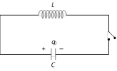
When a charged capacitor C having an initial charge \[{{q}_{0}}\] is discharged through an inductance \[L,\] the charge and current in the circuit start oscillating simple harmonically. If the resistance of the circuit is zero, no energy is dissipated as heat. We also assume an idealized situation in which energy is not radiated away from the circuit. The total energy associated with the circuit is constant.
Frequency of oscillation is given by \[\omega =\frac{1}{\sqrt{LC}}\,\frac{rad}{sec}\]
or \[\nu =\frac{1}{2\pi \sqrt{LC}}Hz\]
With the help of visibility, knowledge about coherence, fringe contrast an interference pattern is obtained.
\[V=\frac{{{I}_{\max }}-{{I}_{\min }}}{{{I}_{\max }}+{{I}_{\min }}}=2\frac{\sqrt{{{I}_{1}}{{I}_{2}}}\,}{({{I}_{1}}+{{I}_{2}})}\] If \[{{I}_{\min }}=0\], \[V=1\] (maximum) i.e., fringe visibility will be best.
Also if \[{{I}_{\max }}=0,\,V=-1\] and If \[{{I}_{\max }}={{I}_{\min }},\,V=0\]
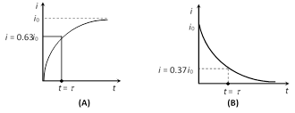
If a circuit containing a pure inductor L and a resistor R in series with a battery and a key then on closing the circuit current through the circuit rises exponentially and reaches up to a certain maximum value (steady state). If circuit is opened from it's steady state condition then current through the circuit decreases exponentially.
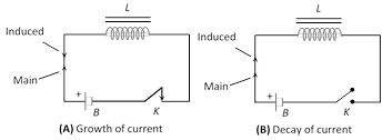 (1) The value of current at any instant of time t after closing the circuit (i.e. during the rising of current) is given by \[i={{i}_{\mathbf{0}}}\left[ \mathbf{1}-{{e}^{-\,\frac{R}{L}t}} \right]\]; where \[{{i}_{0}}={{i}_{\max }}=\frac{E}{R}\]= steady state current.
(2) The value of current at any instant of time t after opening from the steady state condition (i.e. during the decaying of current) is given by \[i={{i}_{\mathbf{0}}}{{e}^{-\,\frac{R}{L}t}}\]
(3) Time constant \[(\tau )\]: It is given as \[\tau =\frac{L}{R}\]; It's unit is second. In other words the time interval, during which the current in an inductive circuit rises to 63% of its maximum value at make, is defined as time constant or it is the time interval, during which the current after opening an inductive circuit falls to 37% of its maximum value.
(1) The value of current at any instant of time t after closing the circuit (i.e. during the rising of current) is given by \[i={{i}_{\mathbf{0}}}\left[ \mathbf{1}-{{e}^{-\,\frac{R}{L}t}} \right]\]; where \[{{i}_{0}}={{i}_{\max }}=\frac{E}{R}\]= steady state current.
(2) The value of current at any instant of time t after opening from the steady state condition (i.e. during the decaying of current) is given by \[i={{i}_{\mathbf{0}}}{{e}^{-\,\frac{R}{L}t}}\]
(3) Time constant \[(\tau )\]: It is given as \[\tau =\frac{L}{R}\]; It's unit is second. In other words the time interval, during which the current in an inductive circuit rises to 63% of its maximum value at make, is defined as time constant or it is the time interval, during which the current after opening an inductive circuit falls to 37% of its maximum value.
 Current Affairs CategoriesArchive
Trending Current Affairs


You need to login to perform this action. |

