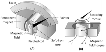
 In a moving coil galvanometer the coil is suspended between the pole pieces of a strong horse-shoe magnet. The pole pieces are made cylindrical and a soft iron cylindrical core is placed within the coil without touching it. This makes the field radial. In such a field the plane of the coil always remains parallel to the field. Therefore \[\theta ={{90}^{o}}\] and the deflecting torque always has the maximum value.
\[{{\tau }_{\text{def}}}=NBiA\] ......(i)
Coil deflects, a restoring torque is set up in the suspension fibre. If \[\alpha \] is the angle of twist, the restoring torque is
\[{{\tau }_{\text{rest}}}=C\alpha \] .....(ii)
where C is the torsional constant of the fibre.
When the coil is in equilibrium \[NBiA=C\alpha \Rightarrow i=Ka,\]
where \[K=\frac{C}{NBA}\] is the galvanometer constant. This linear relationship between i and a makes the moving coil galvanometer useful for current measurement and detection.
Current sensitivity \[\mathbf{(}{{\mathbf{S}}_{\mathbf{i}}}\mathbf{)}\] : The current sensitivity of a galvanometer is defined as the deflection produced in the galvanometer per unit current flowing through it.
\[{{S}_{i}}=\frac{\alpha }{i}=\frac{NBA}{C}\]
Voltage sensitivity \[\mathbf{(}{{\mathbf{S}}_{\mathbf{V}}}\mathbf{)}\] : Voltage sensitivity of a galvanometer is defined as the deflection produced in the galvanometer per unit voltage applied to it.
\[{{S}_{V}}=\frac{\alpha }{V}=\frac{\alpha }{iR}=\frac{{{S}_{i}}}{R}=\frac{NBA}{RC}\]
In a moving coil galvanometer the coil is suspended between the pole pieces of a strong horse-shoe magnet. The pole pieces are made cylindrical and a soft iron cylindrical core is placed within the coil without touching it. This makes the field radial. In such a field the plane of the coil always remains parallel to the field. Therefore \[\theta ={{90}^{o}}\] and the deflecting torque always has the maximum value.
\[{{\tau }_{\text{def}}}=NBiA\] ......(i)
Coil deflects, a restoring torque is set up in the suspension fibre. If \[\alpha \] is the angle of twist, the restoring torque is
\[{{\tau }_{\text{rest}}}=C\alpha \] .....(ii)
where C is the torsional constant of the fibre.
When the coil is in equilibrium \[NBiA=C\alpha \Rightarrow i=Ka,\]
where \[K=\frac{C}{NBA}\] is the galvanometer constant. This linear relationship between i and a makes the moving coil galvanometer useful for current measurement and detection.
Current sensitivity \[\mathbf{(}{{\mathbf{S}}_{\mathbf{i}}}\mathbf{)}\] : The current sensitivity of a galvanometer is defined as the deflection produced in the galvanometer per unit current flowing through it.
\[{{S}_{i}}=\frac{\alpha }{i}=\frac{NBA}{C}\]
Voltage sensitivity \[\mathbf{(}{{\mathbf{S}}_{\mathbf{V}}}\mathbf{)}\] : Voltage sensitivity of a galvanometer is defined as the deflection produced in the galvanometer per unit voltage applied to it.
\[{{S}_{V}}=\frac{\alpha }{V}=\frac{\alpha }{iR}=\frac{{{S}_{i}}}{R}=\frac{NBA}{RC}\]
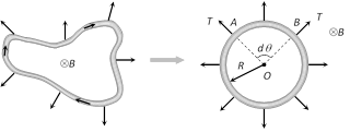
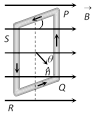 (i) \[\tau \] is zero when \[\theta =0,\] i.e., when the plane of the coil is perpendicular to the field.
(ii) \[\tau \] is maximum when \[\theta ={{90}^{o}}\], i.e., the plane of the coil is parallel to the field \[{{\tau }_{\max }}=NBiA\]
(2) Workdone : If coil is rotated through an angle \[\theta \] from it's equilibrium position then required work. \[W=MB(1-\cos \theta ).\] It is maximum when \[\theta ={{180}^{o}}\Rightarrow {{W}_{\max }}=2MB\]
(3) Potential energy : \[U=-MB\cos \theta \Rightarrow U=-\overrightarrow{M}.\overrightarrow{B}\]
(i) \[\tau \] is zero when \[\theta =0,\] i.e., when the plane of the coil is perpendicular to the field.
(ii) \[\tau \] is maximum when \[\theta ={{90}^{o}}\], i.e., the plane of the coil is parallel to the field \[{{\tau }_{\max }}=NBiA\]
(2) Workdone : If coil is rotated through an angle \[\theta \] from it's equilibrium position then required work. \[W=MB(1-\cos \theta ).\] It is maximum when \[\theta ={{180}^{o}}\Rightarrow {{W}_{\max }}=2MB\]
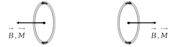
(3) Potential energy : \[U=-MB\cos \theta \Rightarrow U=-\overrightarrow{M}.\overrightarrow{B}\] 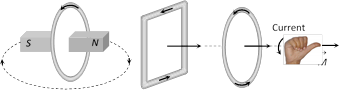 (1) For a given perimeter circular shape have maximum area. Hence maximum magnetic moment.
(2) For a any loop or coil \[\overrightarrow{B}\] at centre due to current in loop, and \[\overrightarrow{M}\] are always parallel.
(1) For a given perimeter circular shape have maximum area. Hence maximum magnetic moment.
(2) For a any loop or coil \[\overrightarrow{B}\] at centre due to current in loop, and \[\overrightarrow{M}\] are always parallel.
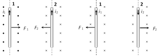
 Case 2 : Equilibrium of a current carrying conductor : When a finite length current carrying wire is kept parallel to another infinite length current carrying wire, it can suspend freely in air as shown below
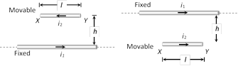 In both the situations for equilibrium of XY it's downward weight = upward magnetic force i.e. \[\mathbf{mg=}\frac{{{\mathbf{\mu }}_{\mathbf{0}}}}{\mathbf{4\pi }}\mathbf{.}\frac{\mathbf{2}{{\mathbf{i}}_{\mathbf{1}}}{{\mathbf{i}}_{\mathbf{2}}}}{\mathbf{h}}\mathbf{.l}\]
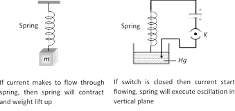
Case 3 : Current carrying spring : If current is passed through a spring, then it will contract because current will flow through all the turns in the same direction.
In both the situations for equilibrium of XY it's downward weight = upward magnetic force i.e. \[\mathbf{mg=}\frac{{{\mathbf{\mu }}_{\mathbf{0}}}}{\mathbf{4\pi }}\mathbf{.}\frac{\mathbf{2}{{\mathbf{i}}_{\mathbf{1}}}{{\mathbf{i}}_{\mathbf{2}}}}{\mathbf{h}}\mathbf{.l}\]
Case 3 : Current carrying spring : If current is passed through a spring, then it will contract because current will flow through all the turns in the same direction.
 Case 4 : Tension less strings : In the following figure the value and direction of current through the conductor XY so that strings becomes tensionless?
Strings becomes tensionless if weight of conductor XY balanced by magnetic force \[({{F}_{m}})\].
Case 4 : Tension less strings : In the following figure the value and direction of current through the conductor XY so that strings becomes tensionless?
Strings becomes tensionless if weight of conductor XY balanced by magnetic force \[({{F}_{m}})\].
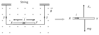 Hence direction of current is from \[X\to Y\] and in balanced condition \[{{F}_{m}}=mg\] \[\Rightarrow \] \[B\,i\,l=mg\] \[\Rightarrow \] \[i=\frac{mg}{B\,l}\]
Case 5 : Sliding of conducting rod on inclined rails : When a conducting rod slides on conducting rails.
Hence direction of current is from \[X\to Y\] and in balanced condition \[{{F}_{m}}=mg\] \[\Rightarrow \] \[B\,i\,l=mg\] \[\Rightarrow \] \[i=\frac{mg}{B\,l}\]
Case 5 : Sliding of conducting rod on inclined rails : When a conducting rod slides on conducting rails.
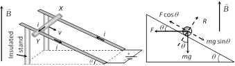 In the following situation conducting rod (X, Y) slides at constant velocity if
\[F\cos \theta =mg\sin \theta \]\[\Rightarrow \]\[B\,i\,l\cos \theta =mg\sin \theta \]\[\Rightarrow \]\[B=\frac{mg}{i\,l}\tan \theta \]
In the following situation conducting rod (X, Y) slides at constant velocity if
\[F\cos \theta =mg\sin \theta \]\[\Rightarrow \]\[B\,i\,l\cos \theta =mg\sin \theta \]\[\Rightarrow \]\[B=\frac{mg}{i\,l}\tan \theta \] 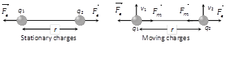 Magnetic force between them is \[{{F}_{m}}=\frac{{{\mu }_{0}}}{4\pi }.\frac{{{q}_{1}}{{q}_{2}}\,{{v}_{1}}{{v}_{2}}}{{{r}^{2}}}\] .... (i)
and Electric force between them is \[{{F}_{e}}=\frac{1}{4\pi {{\varepsilon }_{0}}}.\frac{{{q}_{1}}{{q}_{2}}}{{{r}^{2}}}\] .... (ii)
From equation (i) and (ii) \[\frac{{{F}_{m}}}{{{F}_{e}}}={{\mu }_{0}}{{\varepsilon }_{0}}{{v}^{2}}\] but \[{{\mu }_{0}}{{\varepsilon }_{0}}=\frac{1}{{{c}^{2}}}\];
where c is the velocity of light in vacuum. So \[\frac{{{F}_{m}}}{{{F}_{e}}}={{\left( \frac{v}{c} \right)}^{2}}\]
As \[v<c\] so \[{{F}_{m}}<{{F}_{e}}\]
Magnetic force between them is \[{{F}_{m}}=\frac{{{\mu }_{0}}}{4\pi }.\frac{{{q}_{1}}{{q}_{2}}\,{{v}_{1}}{{v}_{2}}}{{{r}^{2}}}\] .... (i)
and Electric force between them is \[{{F}_{e}}=\frac{1}{4\pi {{\varepsilon }_{0}}}.\frac{{{q}_{1}}{{q}_{2}}}{{{r}^{2}}}\] .... (ii)
From equation (i) and (ii) \[\frac{{{F}_{m}}}{{{F}_{e}}}={{\mu }_{0}}{{\varepsilon }_{0}}{{v}^{2}}\] but \[{{\mu }_{0}}{{\varepsilon }_{0}}=\frac{1}{{{c}^{2}}}\];
where c is the velocity of light in vacuum. So \[\frac{{{F}_{m}}}{{{F}_{e}}}={{\left( \frac{v}{c} \right)}^{2}}\]
As \[v<c\] so \[{{F}_{m}}<{{F}_{e}}\]  Direction of force : If conductors carries current in same direction, then force between them will be attractive. If conductor carries current in opposite direction, then force between them will be repulsive.
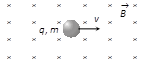 (1) Zero force : Force on charged particle will be zero (i.e. \[F=0\]) if
(i) No field i.e. \[B=0\Rightarrow F=0\]
(ii) Neutral particle i.e. \[q=0\,\Rightarrow F=\text{ }0\]
(iii) Rest charge i.e. \[v=0\,\Rightarrow F=0\]
(iv) Moving charge i.e. \[\theta ={{0}^{o}}\]or \[\theta ={{180}^{o}}\Rightarrow F=0\]
(2) Direction of force : The force \[\overrightarrow{F}\] is always perpendicular to both the velocity \[\overrightarrow{v}\] and the field \[\overrightarrow{B}\] in accordance with Right Hand Screw Rule, though \[\overrightarrow{v}\] and \[\overrightarrow{B}\] themselves may or may not be perpendicular to each other.
(1) Zero force : Force on charged particle will be zero (i.e. \[F=0\]) if
(i) No field i.e. \[B=0\Rightarrow F=0\]
(ii) Neutral particle i.e. \[q=0\,\Rightarrow F=\text{ }0\]
(iii) Rest charge i.e. \[v=0\,\Rightarrow F=0\]
(iv) Moving charge i.e. \[\theta ={{0}^{o}}\]or \[\theta ={{180}^{o}}\Rightarrow F=0\]
(2) Direction of force : The force \[\overrightarrow{F}\] is always perpendicular to both the velocity \[\overrightarrow{v}\] and the field \[\overrightarrow{B}\] in accordance with Right Hand Screw Rule, though \[\overrightarrow{v}\] and \[\overrightarrow{B}\] themselves may or may not be perpendicular to each other.
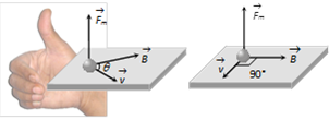 Direction of force on charged particle in magnetic field can also be find by Fleming's Left Hand Rule (FLHR).
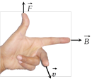 Here, First finger (indicates) \[\to \]Direction of magnetic field
Middle finger \[\to \] Direction of motion of positive charge or direction, Opposite to the motion of negative charge.
Thumb \[\to \] Direction of force
Here, First finger (indicates) \[\to \]Direction of magnetic field
Middle finger \[\to \] Direction of motion of positive charge or direction, Opposite to the motion of negative charge.
Thumb \[\to \] Direction of force 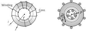 Consider a toroid having n turns per unit length. Magnetic field at a point P in the figure is given as
\[B=\frac{{{\mu }_{0}}Ni}{2\pi r}={{\mu }_{o}}ni\] where \[n=\frac{N}{2\pi r}\]
Consider a toroid having n turns per unit length. Magnetic field at a point P in the figure is given as
\[B=\frac{{{\mu }_{0}}Ni}{2\pi r}={{\mu }_{o}}ni\] where \[n=\frac{N}{2\pi r}\] 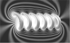 A cylinderical coil of many tightly wound turns of insulated wire with generally diameter of the coil smaller than its length is called a solenoid.
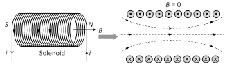 A magnetic field is produced around and within the solenoid. The magnetic field within the solenoid is uniform and parallel to the axis of solenoid.
(1) Finite length solenoid : If \[N=\] total number of turns, \[l=\] length of the solenoid, \[n=\] number of turns per unit length \[=\frac{N}{l}\]
A magnetic field is produced around and within the solenoid. The magnetic field within the solenoid is uniform and parallel to the axis of solenoid.
(1) Finite length solenoid : If \[N=\] total number of turns, \[l=\] length of the solenoid, \[n=\] number of turns per unit length \[=\frac{N}{l}\]
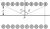 (i) Magnetic field inside the solenoid at point P is given by \[B=\frac{{{\mu }_{0}}}{4\pi }(2\pi \,ni)[\sin \alpha +\sin \beta ]\]
(ii) Infinite length solenoid : If the solenoid is of infinite length and the point is well inside the solenoid i.e. \[\alpha =\beta =(\pi /2)\].
So \[{{B}_{in}}={{\mu }_{0}}ni\]
(iii) If the solenoid is of infinite length and the point is near one end i.e. \[\alpha =0\] and \[\beta =(\pi /2)\] so \[{{B}_{end}}=\frac{1}{2}\mathbf{(}{{\mu }_{\mathbf{0}}}ni\mathbf{)}\] (\[{{B}_{end}}=\frac{1}{2}{{B}_{in}}\])
(i) Magnetic field inside the solenoid at point P is given by \[B=\frac{{{\mu }_{0}}}{4\pi }(2\pi \,ni)[\sin \alpha +\sin \beta ]\]
(ii) Infinite length solenoid : If the solenoid is of infinite length and the point is well inside the solenoid i.e. \[\alpha =\beta =(\pi /2)\].
So \[{{B}_{in}}={{\mu }_{0}}ni\]
(iii) If the solenoid is of infinite length and the point is near one end i.e. \[\alpha =0\] and \[\beta =(\pi /2)\] so \[{{B}_{end}}=\frac{1}{2}\mathbf{(}{{\mu }_{\mathbf{0}}}ni\mathbf{)}\] (\[{{B}_{end}}=\frac{1}{2}{{B}_{in}}\]) 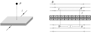 \[\int_{a}^{b}{\overrightarrow{B}.\overrightarrow{dl}}+\int_{b}^{c}{\overrightarrow{B}.\overrightarrow{dl}}+\int_{c}^{d}{\overrightarrow{B}.\overrightarrow{dl}}+\int_{d}^{a}{\overrightarrow{B}.\overrightarrow{dl}}={{\mu }_{0}}i\] (By Ampere's law)
Since \[B\bot dl\] along the path \[b\to c\] and \[d\to a,\] therefore, \[\int_{b}^{c}{\overrightarrow{B}.\overrightarrow{dl}}=0\]; \[\int_{d}^{a}{\overrightarrow{B}.\overrightarrow{dl}}=0\]
Also, \[B\,\,|\,\,|\,\,dl\] along the path \[a\to b\] and \[c\to d,\] thus \[\int_{a}^{b}{\overrightarrow{B}.\overrightarrow{dl}}+\int_{d}^{a}{\overrightarrow{B}.\overrightarrow{dl}}=2Bl\]
The current enclosed by the loop is \[i=jl\]. Therefore, according to Ampere?s law \[2Bl={{\mu }_{0}}(jl)\] or \[B=\frac{{{\mu }_{0}}j}{2}\]
\[\int_{a}^{b}{\overrightarrow{B}.\overrightarrow{dl}}+\int_{b}^{c}{\overrightarrow{B}.\overrightarrow{dl}}+\int_{c}^{d}{\overrightarrow{B}.\overrightarrow{dl}}+\int_{d}^{a}{\overrightarrow{B}.\overrightarrow{dl}}={{\mu }_{0}}i\] (By Ampere's law)
Since \[B\bot dl\] along the path \[b\to c\] and \[d\to a,\] therefore, \[\int_{b}^{c}{\overrightarrow{B}.\overrightarrow{dl}}=0\]; \[\int_{d}^{a}{\overrightarrow{B}.\overrightarrow{dl}}=0\]
Also, \[B\,\,|\,\,|\,\,dl\] along the path \[a\to b\] and \[c\to d,\] thus \[\int_{a}^{b}{\overrightarrow{B}.\overrightarrow{dl}}+\int_{d}^{a}{\overrightarrow{B}.\overrightarrow{dl}}=2Bl\]
The current enclosed by the loop is \[i=jl\]. Therefore, according to Ampere?s law \[2Bl={{\mu }_{0}}(jl)\] or \[B=\frac{{{\mu }_{0}}j}{2}\] 


You need to login to perform this action.
You will be redirected in
3 sec

