(1) Resistivity : From \[R=\rho \frac{l}{A};\] If \[l=1m,\,\,A=1\,{{m}^{2}}\] then \[R=\rho \] i.e. resistivity is numerically equal to the resistance of a substance having unit area of cross-section and unit length.
(i) Unit and dimension : It's S.I. unit is ohm \[\times \] m and dimension is \[[M{{L}^{3}}{{T}^{-3}}{{A}^{-2}}]\]
(ii) It's formula : \[\rho =\frac{m}{n{{e}^{2}}\tau }\]
(iii) Resistivity is the intrinsic property of the substance. It is independent of shape and size of the body (i.e. \[l\] and \[A\]).
(iv) For different substances their resistivity is also different e.g. \[{{\rho }_{\text{silver}}}=\] minimum \[=1.6\times {{10}^{-8}}\,\,\Omega -m\] and \[{{\rho }_{\text{fused quartz}}}=\] maximum \[\approx {{10}^{16}}\,\,\Omega -m\]W
\[\underset{\mathbf{(Maximum for fused quartz)}}{\mathop{{{\rho }_{\mathbf{insulator}}}}}\,>{{\rho }_{\mathbf{alloy}}}>{{\rho }_{\mathbf{semi-conductor}}}>\underset{\mathbf{(Minimum for silver})}{\mathop{{{\rho }_{\mathbf{conductor}}}}}\,\]
(v) Resistivity depends on the temperature. For metals \[{{\rho }_{t}}={{\rho }_{0}}(1+\alpha \Delta t)\] i.e. resitivity increases with temperature.
(vi) Resistivity increases with impurity and mechanical stress.
(vii) Magnetic field increases the resistivity of all metals except iron, cobalt and nickel.
(viii) Resistivity of certain substances like selenium, cadmium, sulphides is inversely proportional to intensity of light falling upon them.
(2) Conductivity : Reciprocal of resistivity is called conductivity \[(\sigma )\] i.e. \[\sigma =\frac{1}{\rho }\] with unit mho/m and dimensions \[[{{M}^{-1}}{{L}^{-3}}{{T}^{3}}{{A}^{2}}]\].
(3) Conductance : Reciprocal of resistance is known as conductance. \[C=\frac{1}{R}\] It's unit is \[\frac{1}{\Omega }\] or \[{{\Omega }^{-1}}\] or 'Siemen'.
(1) The property of substance by virtue of which it opposes the flow of current through it, is known as the resistance.
(2) Formula of resistance : For a conductor if \[l=\] length of a conductor \[A=\] Area of cross-section of conductor, \[n=\] No. of free electrons per unit volume in conductor, \[\tau =\] relaxation time then resistance of conductor \[R=\rho \frac{l}{A}=\frac{m}{n{{e}^{\mathbf{2}}}\tau }.\frac{l}{A}\]; where \[\rho =\] resistivity of the material of conductor
(3) Unit and dimension : It's S.I. unit is Volt/Amp. or Ohm \[(\Omega )\]. Also 1 ohm \[=\frac{1volt}{1Amp}=\frac{{{10}^{8}}emu\,\text{of potential}}{\text{1}{{\text{0}}^{-\text{1}}}emu\,\text{of current }}\]\[={{10}^{9}}\]emu of resistance. It?s dimension is \[[M{{L}^{2}}{{T}^{-3}}{{A}^{-2}}]\].
(4) Dependence of resistance : Resistance of a conductor depends upon the following factors.
(i) Length of the conductor : Resistance of a conductor is directly proportional to it's length i.e. \[R\propto l\] and inversely proportional to it's area of cross-section i.e. \[R\propto \frac{1}{A}\]
(ii) Temperature : For a conductor
Resistance \[\propto \] temperature.
If \[{{R}_{0}}=\] resistance of conductor at
\[{{0}^{o}}C\] \[{{R}_{t}}=\] resistance of conductor at \[{{t}^{o}}C\]
and \[\alpha ,\,\,\beta =\] temperature co-efficient of resistance
then \[{{R}_{t}}={{R}_{0}}(1+\alpha \,t+\beta \,{{t}^{2}})\] for \[t>{{300}^{o}}C\] and
\[{{R}_{t}}={{R}_{0}}(1+\alpha t)\] for \[t\le {{300}^{o}}C\] or \[\alpha =\frac{{{R}_{t}}-{{R}_{0}}}{{{R}_{0}}\times t}\]
If \[{{R}_{1}}\] and \[{{R}_{2}}\] are the resistances at \[{{t}_{1}}^{o}C\] and \[{{t}_{2}}^{o}C\] respectively then \[\frac{{{R}_{1}}}{{{R}_{2}}}=\frac{1+\alpha \,{{t}_{1}}}{1+\alpha \,{{t}_{2}}}\].
The value of \[\alpha \] is different at different temperature. Temperature coefficient of resistance averaged over the temperature range \[{{t}_{1}}{{\,}^{o}}C\] to \[{{t}_{2}}{{\,}^{o}}C\] is given by \[\alpha =\frac{{{R}_{2}}-{{R}_{1}}}{{{R}_{1}}({{t}_{2}}-{{t}_{1}})}\] which gives \[{{R}_{2}}={{R}_{1}}[1+\alpha ({{t}_{2}}-{{t}_{1}})]\]. This formula gives an approximate value.
Variation of resistance of some electrical material with temperature
Material
Temp. coefficient of resistance \[\mathbf{(\alpha )}\]
If the physical conditions of the conductor (length, temperature, mechanical strain etc.) remains some, then the current flowing through the conductor is directly proportional to the potential difference across it's two ends i.e. \[i\propto V\] \[\Rightarrow \] \[V=iR\] where R is a proportionality constant, known as electric resistance.
(1) Ohm's law is not a universal law, the substances, which obey ohm's law are known as ohmic substance.
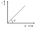
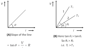
(2) Graph between V and i for a metallic conductor is a straight line as shown. At different temperatures V-i curves are different.
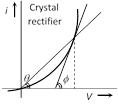
(3) The device or substances which don't obey ohm's law e.g. gases, crystal rectifiers, thermoionic valve, transistors etc. are known as non-ohmic or non-linear conductors. For these V-i curve is not linear.
Static resistance \[{{R}_{st}}=\frac{V}{i}=\frac{1}{\tan \theta }\]
Dynamic resistance \[{{R}_{dyn}}=\frac{\Delta V}{\Delta I}=\frac{1}{\tan \varphi }\]
Drift velocity is the average uniform velocity acquired by free electrons inside a metal by the application of an electric field which is responsible for current through it. Drift velocity is very small it is of the order of \[{{10}^{-4}}\,m/s\] as compared to thermal speed \[(\tilde{}\,{{10}^{5}}\,m/s)\] of electrons at room temperature.
If suppose for a conductor
n = Number of electron per unit volume of the conductor
A = Area of cross-section
V = potential difference across the conductor
E = electric field inside the conductor
i = current, J = current density, \[\rho =\] specific resistance, \[\sigma =\] conductivity \[\left( \sigma =\frac{1}{\rho } \right)\] then current relates with drift velocity as \[i=neA{{v}_{d}}\] we can also write
\[{{v}_{d}}=\frac{i}{neA}=\frac{J}{ne}=\frac{\sigma E}{ne}=\frac{E}{\rho ne}=\frac{V}{\rho \,l\,n\,e}\].
(1) The direction of drift velocity for electron in a metal is opposite to that of applied electric field (i.e. current density \[\vec{J}\]).
\[{{v}_{d}}\propto E\] i.e., greater the electric field, larger will be the drift velocity.
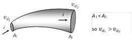
(2) When a steady current flows through a conductor of non-uniform cross-section drift velocity varies inversely with area of cross-section \[\left( {{v}_{d}}\propto \frac{1}{A} \right)\]
(3) If diameter (d) of a conductor is doubled, then drift velocity of electrons inside it will not change.
(1) Relaxation time \[\mathbf{(\tau )}\] : The time interval between two successive collisions of electrons with the positive ions in the metallic lattice is defined as relaxation time
\[\tau =\frac{\text{mean free path}}{\text{r}\text{.m}\text{.s}\text{. velocity of electrons }}=\frac{\lambda }{{{v}_{rms}}}\]. With rise in temperature \[{{v}_{rms}}\] increases consequently \[\tau \] decreases.
(2) Mobility : Drift velocity per unit electric field is called mobility of electron i.e. \[\mu =\frac{{{v}_{d}}}{E}\]. It?s unit is \[\frac{{{m}^{2}}}{volt-\sec }\].
Current density at any point inside a conductor is defined as a vector having magnitude equal to current per unit area surrounding that point. Remember area is normal to the direction of charge flow (or current passes) through that point.
(1) Current density at point P is given by \[\overrightarrow{J\,}=\frac{di}{dA}\overrightarrow{n\,}\]
(2) If the cross-sectional area is not normal to the current, but makes an angle \[\theta \] with the direction of current then
\[J=\frac{di}{dA\cos \theta }\] \[\Rightarrow \] \[di=JdA\cos \theta \] \[=\overrightarrow{J\,}.\overrightarrow{dA}\]\[\Rightarrow \] \[i=\int{\overrightarrow{J\,}\cdot \,\overrightarrow{dA}}\]
(3) If current density \[\overrightarrow{J\,}\] is uniform for a normal cross-section \[\overrightarrow{A\,}\] then \[J=\frac{i}{A}\]
(4) Current density \[\overrightarrow{J\,}\] is a vector quantity. It's direction is same as that of \[\overrightarrow{E}\] . It's S.I. unit is \[amp/{{m}^{2}}\] and dimension \[[{{L}^{-2}}A]\].
(5) In case of uniform flow of charge through a cross-section normal to it as \[i=nqvA\] \[\Rightarrow \]\[J=\frac{i}{A}=nqv\].
(6) Current density relates with electric field as \[\overrightarrow{J}=\sigma \,\overrightarrow{E}=\frac{\overrightarrow{E}}{\rho }\]; where \[\sigma =\] conductivity and \[\rho =\] resistivity or specific resistance of substance.
(1) The time rate of flow of charge through any cross-section is called current. \[i=\underset{\text{ }\!\!\Delta\!\!\text{ }t\to 0}{\mathop{Lim}}\,\frac{\text{ }\!\!\Delta\!\!\text{ }Q}{\text{ }\!\!\Delta\!\!\text{ }t}=\frac{dQ}{dt}\]. If flow is uniform then \[i=\frac{Q}{t}\]. Current is a scalar quantity. It's S.I. unit is ampere (A) and C.G.S. unit is emu and is called biot (Bi), or ab ampere. 1A = (1/10) Bi (ab amp.)
(2) Ampere of current means the flow of \[6.25\times {{10}^{18}}\] electrons/sec through any cross-section of the conductor.
(3) The conventional direction of current is taken to be the direction of flow of positive charge, i.e. field and is opposite to the direction of flow of negative charge as shown below.
(4) The net charge in a current carrying conductor is zero.
(5) For a given conductor current does not change with change in cross-sectional area. In the following figure \[{{i}_{1}}={{i}_{2}}={{i}_{3}}\]
(6) Current due to translatory motion of charge : If n particle each having a charge q, pass through a given area in time t then \[i=\frac{nq}{t}\]
If n particles each having a charge q pass per second per unit area, the current associated with cross-sectional area A is \[i=nqA\]
If there are n particle per unit volume each having a charge q and moving with velocity v, the current thorough, cross section A is \[i=nqvA\]
Types of current
Alternating current (ac)
Direct current (dc)
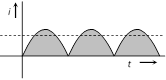
(i) Magnitude and direction both varies with time
\[ac\to \text{Rectifier}\to dc\]
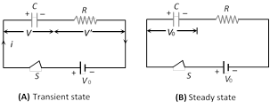
As shown in the following figure (A) when switch S is closed, capacitor start charging. In this transient state potential difference appears across capacitor as well as resistor. When capacitor gets fully charged the entire potential difference appeared across the capacitor and nothing is left for the resistor. [Shown in figure (B)]
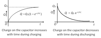
(i) Charging : In transient state of charging charge on the capacitor at any instant \[Q={{Q}_{0}}\,\left( 1-{{e}^{\frac{-t}{RC}}} \right)\] and potential difference across the capacitor at any instant \[V={{V}_{0}}\,\left( 1-{{e}^{\frac{-t}{RC}}} \right)\]
(Here Q and V are the instantaneous values of charge and potential difference while maximum charge on capacitor is \[{{Q}_{0}}=C{{V}_{0}}\])
(ii) Discharging : After the completion of charging, if battery is removed capacitor starts discharging. In transient state charge on the capacitor at any instant \[Q={{Q}_{0}}{{e}^{-t/RC}}\] and potential difference cross the capacitor at any instant \[V={{V}_{0}}{{e}^{-t/CR}}\].
(iii) Time constant \[(\tau )\]: The quantity RC is called the time constant as it has the dimension of time during charging if \[t=\tau =RC\], \[Q={{Q}_{0}}(1-{{e}^{-1}})=0.63\,{{Q}_{0}}=63%\] of \[{{Q}_{0}}\,(\frac{1}{e}=0.37)\] or during discharging it is defined as the time during which charge on a capacitor falls to 0.37 times (37%) of the initial charge on the capacitor.
(1) Series grouping
(i) Charge on each capacitor remains same and equals to the main charge supplied by the battery but potential difference distributes i.e. \[V={{V}_{1}}+{{V}_{2}}+{{V}_{3}}\]
(ii) Equivalent capacitance
\[\frac{1}{{{C}_{eq}}}=\frac{1}{{{C}_{1}}}+\frac{1}{{{C}_{2}}}+\frac{1}{{{C}_{3}}}\] or \[{{C}_{eq}}={{(C_{1}^{-1}+C_{2}^{-1}+C_{3}^{-1})}^{-1}}\]
(iii) In series combination potential difference and energy distributes in the reverse ratio of capacitance i.e.,
\[V\propto \frac{1}{C}\] and \[U\propto \frac{1}{C}\].
(iv) If two capacitors having capacitances \[{{C}_{1}}\] and \[{{C}_{2}}\] are connected in series then \[{{C}_{eq}}=\frac{{{C}_{\mathbf{1}}}{{C}_{\mathbf{2}}}}{{{C}_{\mathbf{1}}}+{{C}_{\mathbf{2}}}}=\frac{Multiplication}{Addition}\]
\[{{V}_{1}}=\left( \frac{{{C}_{2}}}{{{C}_{1}}+{{C}_{2}}} \right)\,.\,V\] and \[{{V}_{2}}=\left( \frac{{{C}_{1}}}{{{C}_{1}}+{{C}_{2}}} \right)\,.\,V\]
(v) If \[n\] identical capacitors each having capacitances C are connected in series with supply voltage V then Equivalent capacitance \[{{C}_{eq}}=\frac{C}{n}\,\] and Potential difference across each capacitor \[V'=\frac{V}{n}\].
(vi) If \[n\] identical plates are arranged as shown below, they constitute \[(n-1)\] capacitors in series. If each capacitors having capacitance \[\frac{{{\varepsilon }_{0}}A}{d}\] then \[{{C}_{eq}}=\frac{{{\varepsilon }_{0}}A}{(n-1)d}\]
In this situation except two extreme plates each plate is common to adjacent capacitors.
(2) Parallel grouping
(i) Potential difference across each capacitor remains same and equal to the applied potential difference but charge distributes i.e. \[Q={{Q}_{1}}+{{Q}_{2}}+{{Q}_{3}}\]
(ii) \[{{C}_{-eq}}={{C}_{1}}+{{C}_{2}}+{{C}_{3}}\]
(iii) In parallel combination charge and energy distributes in the ratio of capacitance i.e. \[Q\,\,\propto \,\,C\] and \[U\,\,\propto \,\,C\]
(iv) If two capacitors having capacitance \[{{C}_{1}}\] and \[{{C}_{2}}\] respectively are connected in parallel then \[{{C}_{eq}}={{C}_{1}}+{{C}_{2}}\]
\[{{Q}_{1}}=\left( \frac{{{C}_{1}}}{{{C}_{1}}+{{C}_{2}}} \right)\,.\,Q\] and \[{{Q}_{2}}=\,\left( \frac{{{C}_{2}}}{{{C}_{1}}+{{C}_{2}}} \right)\,.\,Q\]
(v) If \[n\] identical capacitors are connected in parallel Equivalent capacitance \[{{C}_{eq}}=nC\] and Charge on each capacitor \[Q'=\frac{Q}{n}\]
If \[n\] identical plates are arranged such that even numbered of plates are connected together and odd numbered plates are connected together, then \[(n-1)\] capacitors will be formed and they will be in parallel grouping.
Equivalent capacitance \[C'=(n-1)\,C\] where \[C=\] capacitance of a capacitor \[=\frac{{{\varepsilon }_{0}}A}{d}\]
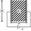
(1) Parallel plate capacitor : It consists of two parallel metallic plates (may be circular, rectangular, square) separated by a small distance. If A = Effective overlapping area of each plate.
(i) Electric field between the plates : \[E=\frac{\sigma }{{{\varepsilon }_{0}}}=\frac{Q}{A{{\varepsilon }_{0}}}\]
(ii) Potential difference between the plates : \[V=E\times d=\frac{\sigma \,d}{{{\varepsilon }_{0}}}\]
(iii) Capacitance : \[C=\frac{{{\varepsilon }_{\mathbf{0}}}A}{d}\]. In C.G.S. : \[C=\frac{A}{\mathbf{4}\pi d}\]
(iv) If a dielectric medium of dielectric constant K is filled completely between the plates then capacitance increases by K times i.e. \[C'=\frac{K{{\varepsilon }_{0}}A}{d}\] \[\Rightarrow \]\[C'=KC\]
(v) The capacitance of parallel plate capacitor depends on \[A(C\,\propto A)\] and \[d\,\left( C\propto \frac{1}{d} \right)\]. It does not depend on the charge on the plates or the potential difference between the plates.
(vi) If a dielectric slab is partially filled between the plates
\[\Rightarrow \] \[C'=\frac{{{\varepsilon }_{0}}A}{d-t+\frac{t}{K}}\]
(vii) If a number of dielectric slabs are inserted between the plate as shown
\[C'=\frac{{{\varepsilon }_{0}}A}{d-({{t}_{1}}+{{t}_{2}}+{{t}_{3}}+........)+\left( \frac{{{t}_{1}}}{{{K}_{1}}}+\frac{{{t}_{2}}}{{{K}_{2}}}+\frac{{{t}_{3}}}{{{K}_{3}}}+........ \right)}\]
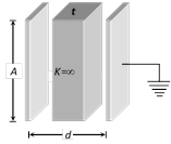
(viii) When a metallic slab is inserted between the plates \[C'=\frac{{{\varepsilon }_{0}}A}{(d-t)}\]
If metallic slab fills the complete space between the plates (i.e. \[t=d\]) or both plates are joined through a metallic wire then capacitance becomes infinite.
(ix) Force between the plates of a parallel plate capacitor.
\[|F|\,=\frac{{{\sigma }^{2}}A}{2{{\varepsilon }_{0}}}=\frac{{{Q}^{2}}}{2{{\varepsilon }_{0}}A}=\frac{C{{V}^{2}}}{2d}\]
(x) Energy density between the plates of a parallel plate capacitor.
Energy density \[=\frac{Energy}{Volume}\]\[=\frac{1}{2}\,{{\varepsilon }_{0}}{{E}^{2}}.\]
Variation of different variable (Q, C, V, E and U) of parallel plate capacitor
Dielectrics are insulating (non-conducting) materials which transmits electric effect without conducting.
Dielectrics are of two types
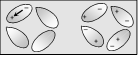
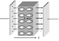
(1) Polar dielectrics : A polar molecule has permanent electric dipole moment \[(\vec{p})\] in the absence of electric field also. But a polar dielectric has net dipole moment zero in the absence of electric field because polar molecules are randomly oriented as shown in figure.
In the presence of electric field polar molecules tends to line up in the direction of electric field, and the substance has finite dipole moment e.g. water, Alcohol, \[C{{O}_{2}}\], \[N{{H}_{3}}\], HCl etc. are made of polar atoms/molecules.
(2) Non polar dielectric : In non-polar molecules, Each molecule has zero dipole moment in its normal state.
When electric field is applied, molecules becomes induced electric dipole e.g. \[{{N}_{2}}\], \[{{O}_{2}}\], Benzene, Methane etc. are made of non-polar atoms/molecules
In general, any non-conducting, material can be called as a dielectric but broadly non conducting material having non polar molecules referred to as dielectric.
(3) Polarization of a dielectric slab : It is the process of inducing equal and opposite charges on the two faces of the dielectric on the application of electric field.
(i) Electric field between the plates in the presence of dielectric medium is \[E'=E-{{E}_{i}}\] where E = Main field, E' = Induced field.
(ii) Dielectric constant of dielectric medium is defined as :
\[\frac{E}{E'}=\frac{\text{Electric field between the plates with air}}{\text{Electric field between the plates with medium}}=K\]
(iii) K is also known as relative permittivity \[({{\varepsilon }_{r}})\] of the material or SIC (Specific Inductive Capacitance)
(4) Dielectric breakdown and dielectric strength : If a very high electric field is created in a dielectric,. The dielectric then behaves like a conductor. This phenomenon is known as dielectric breakdown.
The maximum value of electric field (or potential gradient) that a dielectric material can tolerate without it's electric breakdown is called it's dielectric strength.
S.I. unit of dielectric strength of a material is \[\frac{V}{m}\] but practical unit is \[\frac{kV}{mm}\].
 (3) The device or substances which don't obey ohm's law e.g. gases, crystal rectifiers, thermoionic valve, transistors etc. are known as non-ohmic or non-linear conductors. For these V-i curve is not linear.
 Static resistance \[{{R}_{st}}=\frac{V}{i}=\frac{1}{\tan \theta }\]
Dynamic resistance \[{{R}_{dyn}}=\frac{\Delta V}{\Delta I}=\frac{1}{\tan \varphi }\]
Static resistance \[{{R}_{st}}=\frac{V}{i}=\frac{1}{\tan \theta }\]
Dynamic resistance \[{{R}_{dyn}}=\frac{\Delta V}{\Delta I}=\frac{1}{\tan \varphi }\] 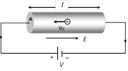 If suppose for a conductor
n = Number of electron per unit volume of the conductor
A = Area of cross-section
V = potential difference across the conductor
E = electric field inside the conductor
i = current, J = current density, \[\rho =\] specific resistance, \[\sigma =\] conductivity \[\left( \sigma =\frac{1}{\rho } \right)\] then current relates with drift velocity as \[i=neA{{v}_{d}}\] we can also write
\[{{v}_{d}}=\frac{i}{neA}=\frac{J}{ne}=\frac{\sigma E}{ne}=\frac{E}{\rho ne}=\frac{V}{\rho \,l\,n\,e}\].
(1) The direction of drift velocity for electron in a metal is opposite to that of applied electric field (i.e. current density \[\vec{J}\]).
\[{{v}_{d}}\propto E\] i.e., greater the electric field, larger will be the drift velocity.
(2) When a steady current flows through a conductor of non-uniform cross-section drift velocity varies inversely with area of cross-section \[\left( {{v}_{d}}\propto \frac{1}{A} \right)\]
If suppose for a conductor
n = Number of electron per unit volume of the conductor
A = Area of cross-section
V = potential difference across the conductor
E = electric field inside the conductor
i = current, J = current density, \[\rho =\] specific resistance, \[\sigma =\] conductivity \[\left( \sigma =\frac{1}{\rho } \right)\] then current relates with drift velocity as \[i=neA{{v}_{d}}\] we can also write
\[{{v}_{d}}=\frac{i}{neA}=\frac{J}{ne}=\frac{\sigma E}{ne}=\frac{E}{\rho ne}=\frac{V}{\rho \,l\,n\,e}\].
(1) The direction of drift velocity for electron in a metal is opposite to that of applied electric field (i.e. current density \[\vec{J}\]).
\[{{v}_{d}}\propto E\] i.e., greater the electric field, larger will be the drift velocity.
(2) When a steady current flows through a conductor of non-uniform cross-section drift velocity varies inversely with area of cross-section \[\left( {{v}_{d}}\propto \frac{1}{A} \right)\]
 (3) If diameter (d) of a conductor is doubled, then drift velocity of electrons inside it will not change.
 (1) Relaxation time \[\mathbf{(\tau )}\] : The time interval between two successive collisions of electrons with the positive ions in the metallic lattice is defined as relaxation time
\[\tau =\frac{\text{mean free path}}{\text{r}\text{.m}\text{.s}\text{. velocity of electrons }}=\frac{\lambda }{{{v}_{rms}}}\]. With rise in temperature \[{{v}_{rms}}\] increases consequently \[\tau \] decreases.
(2) Mobility : Drift velocity per unit electric field is called mobility of electron i.e. \[\mu =\frac{{{v}_{d}}}{E}\]. It?s unit is \[\frac{{{m}^{2}}}{volt-\sec }\].
(1) Relaxation time \[\mathbf{(\tau )}\] : The time interval between two successive collisions of electrons with the positive ions in the metallic lattice is defined as relaxation time
\[\tau =\frac{\text{mean free path}}{\text{r}\text{.m}\text{.s}\text{. velocity of electrons }}=\frac{\lambda }{{{v}_{rms}}}\]. With rise in temperature \[{{v}_{rms}}\] increases consequently \[\tau \] decreases.
(2) Mobility : Drift velocity per unit electric field is called mobility of electron i.e. \[\mu =\frac{{{v}_{d}}}{E}\]. It?s unit is \[\frac{{{m}^{2}}}{volt-\sec }\]. 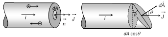 (2) If the cross-sectional area is not normal to the current, but makes an angle \[\theta \] with the direction of current then
\[J=\frac{di}{dA\cos \theta }\] \[\Rightarrow \] \[di=JdA\cos \theta \] \[=\overrightarrow{J\,}.\overrightarrow{dA}\]\[\Rightarrow \] \[i=\int{\overrightarrow{J\,}\cdot \,\overrightarrow{dA}}\]
(3) If current density \[\overrightarrow{J\,}\] is uniform for a normal cross-section \[\overrightarrow{A\,}\] then \[J=\frac{i}{A}\]
(4) Current density \[\overrightarrow{J\,}\] is a vector quantity. It's direction is same as that of \[\overrightarrow{E}\] . It's S.I. unit is \[amp/{{m}^{2}}\] and dimension \[[{{L}^{-2}}A]\].
(5) In case of uniform flow of charge through a cross-section normal to it as \[i=nqvA\] \[\Rightarrow \]\[J=\frac{i}{A}=nqv\].
(6) Current density relates with electric field as \[\overrightarrow{J}=\sigma \,\overrightarrow{E}=\frac{\overrightarrow{E}}{\rho }\]; where \[\sigma =\] conductivity and \[\rho =\] resistivity or specific resistance of substance.
(2) If the cross-sectional area is not normal to the current, but makes an angle \[\theta \] with the direction of current then
\[J=\frac{di}{dA\cos \theta }\] \[\Rightarrow \] \[di=JdA\cos \theta \] \[=\overrightarrow{J\,}.\overrightarrow{dA}\]\[\Rightarrow \] \[i=\int{\overrightarrow{J\,}\cdot \,\overrightarrow{dA}}\]
(3) If current density \[\overrightarrow{J\,}\] is uniform for a normal cross-section \[\overrightarrow{A\,}\] then \[J=\frac{i}{A}\]
(4) Current density \[\overrightarrow{J\,}\] is a vector quantity. It's direction is same as that of \[\overrightarrow{E}\] . It's S.I. unit is \[amp/{{m}^{2}}\] and dimension \[[{{L}^{-2}}A]\].
(5) In case of uniform flow of charge through a cross-section normal to it as \[i=nqvA\] \[\Rightarrow \]\[J=\frac{i}{A}=nqv\].
(6) Current density relates with electric field as \[\overrightarrow{J}=\sigma \,\overrightarrow{E}=\frac{\overrightarrow{E}}{\rho }\]; where \[\sigma =\] conductivity and \[\rho =\] resistivity or specific resistance of substance. 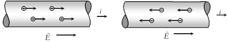 (4) The net charge in a current carrying conductor is zero.
(5) For a given conductor current does not change with change in cross-sectional area. In the following figure \[{{i}_{1}}={{i}_{2}}={{i}_{3}}\]
(4) The net charge in a current carrying conductor is zero.
(5) For a given conductor current does not change with change in cross-sectional area. In the following figure \[{{i}_{1}}={{i}_{2}}={{i}_{3}}\]
 If n particles each having a charge q pass per second per unit area, the current associated with cross-sectional area A is \[i=nqA\]
If there are n particle per unit volume each having a charge q and moving with velocity v, the current thorough, cross section A is \[i=nqvA\]
Types of current
If n particles each having a charge q pass per second per unit area, the current associated with cross-sectional area A is \[i=nqA\]
If there are n particle per unit volume each having a charge q and moving with velocity v, the current thorough, cross section A is \[i=nqvA\]
Types of current


 \[ac\to \text{Rectifier}\to dc\]
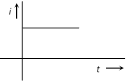
 (Constant dc)
 \[dc\to \text{Inverter}\to ac\]
 (i) Charging : In transient state of charging charge on the capacitor at any instant \[Q={{Q}_{0}}\,\left( 1-{{e}^{\frac{-t}{RC}}} \right)\] and potential difference across the capacitor at any instant \[V={{V}_{0}}\,\left( 1-{{e}^{\frac{-t}{RC}}} \right)\]
(Here Q and V are the instantaneous values of charge and potential difference while maximum charge on capacitor is \[{{Q}_{0}}=C{{V}_{0}}\])
(ii) Discharging : After the completion of charging, if battery is removed capacitor starts discharging. In transient state charge on the capacitor at any instant \[Q={{Q}_{0}}{{e}^{-t/RC}}\] and potential difference cross the capacitor at any instant \[V={{V}_{0}}{{e}^{-t/CR}}\].
(i) Charging : In transient state of charging charge on the capacitor at any instant \[Q={{Q}_{0}}\,\left( 1-{{e}^{\frac{-t}{RC}}} \right)\] and potential difference across the capacitor at any instant \[V={{V}_{0}}\,\left( 1-{{e}^{\frac{-t}{RC}}} \right)\]
(Here Q and V are the instantaneous values of charge and potential difference while maximum charge on capacitor is \[{{Q}_{0}}=C{{V}_{0}}\])
(ii) Discharging : After the completion of charging, if battery is removed capacitor starts discharging. In transient state charge on the capacitor at any instant \[Q={{Q}_{0}}{{e}^{-t/RC}}\] and potential difference cross the capacitor at any instant \[V={{V}_{0}}{{e}^{-t/CR}}\].
 (iii) Time constant \[(\tau )\]: The quantity RC is called the time constant as it has the dimension of time during charging if \[t=\tau =RC\], \[Q={{Q}_{0}}(1-{{e}^{-1}})=0.63\,{{Q}_{0}}=63%\] of \[{{Q}_{0}}\,(\frac{1}{e}=0.37)\] or during discharging it is defined as the time during which charge on a capacitor falls to 0.37 times (37%) of the initial charge on the capacitor.
 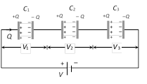 (iii) In series combination potential difference and energy distributes in the reverse ratio of capacitance i.e.,
\[V\propto \frac{1}{C}\] and \[U\propto \frac{1}{C}\].
(iv) If two capacitors having capacitances \[{{C}_{1}}\] and \[{{C}_{2}}\] are connected in series then \[{{C}_{eq}}=\frac{{{C}_{\mathbf{1}}}{{C}_{\mathbf{2}}}}{{{C}_{\mathbf{1}}}+{{C}_{\mathbf{2}}}}=\frac{Multiplication}{Addition}\]
\[{{V}_{1}}=\left( \frac{{{C}_{2}}}{{{C}_{1}}+{{C}_{2}}} \right)\,.\,V\] and \[{{V}_{2}}=\left( \frac{{{C}_{1}}}{{{C}_{1}}+{{C}_{2}}} \right)\,.\,V\]
(v) If \[n\] identical capacitors each having capacitances C are connected in series with supply voltage V then Equivalent capacitance \[{{C}_{eq}}=\frac{C}{n}\,\] and Potential difference across each capacitor \[V'=\frac{V}{n}\].
(vi) If \[n\] identical plates are arranged as shown below, they constitute \[(n-1)\] capacitors in series. If each capacitors having capacitance \[\frac{{{\varepsilon }_{0}}A}{d}\] then \[{{C}_{eq}}=\frac{{{\varepsilon }_{0}}A}{(n-1)d}\]
(iii) In series combination potential difference and energy distributes in the reverse ratio of capacitance i.e.,
\[V\propto \frac{1}{C}\] and \[U\propto \frac{1}{C}\].
(iv) If two capacitors having capacitances \[{{C}_{1}}\] and \[{{C}_{2}}\] are connected in series then \[{{C}_{eq}}=\frac{{{C}_{\mathbf{1}}}{{C}_{\mathbf{2}}}}{{{C}_{\mathbf{1}}}+{{C}_{\mathbf{2}}}}=\frac{Multiplication}{Addition}\]
\[{{V}_{1}}=\left( \frac{{{C}_{2}}}{{{C}_{1}}+{{C}_{2}}} \right)\,.\,V\] and \[{{V}_{2}}=\left( \frac{{{C}_{1}}}{{{C}_{1}}+{{C}_{2}}} \right)\,.\,V\]
(v) If \[n\] identical capacitors each having capacitances C are connected in series with supply voltage V then Equivalent capacitance \[{{C}_{eq}}=\frac{C}{n}\,\] and Potential difference across each capacitor \[V'=\frac{V}{n}\].
(vi) If \[n\] identical plates are arranged as shown below, they constitute \[(n-1)\] capacitors in series. If each capacitors having capacitance \[\frac{{{\varepsilon }_{0}}A}{d}\] then \[{{C}_{eq}}=\frac{{{\varepsilon }_{0}}A}{(n-1)d}\]
 (ii) \[{{C}_{-eq}}={{C}_{1}}+{{C}_{2}}+{{C}_{3}}\]
(iii) In parallel combination charge and energy distributes in the ratio of capacitance i.e. \[Q\,\,\propto \,\,C\] and \[U\,\,\propto \,\,C\]
(iv) If two capacitors having capacitance \[{{C}_{1}}\] and \[{{C}_{2}}\] respectively are connected in parallel then \[{{C}_{eq}}={{C}_{1}}+{{C}_{2}}\]
\[{{Q}_{1}}=\left( \frac{{{C}_{1}}}{{{C}_{1}}+{{C}_{2}}} \right)\,.\,Q\] and \[{{Q}_{2}}=\,\left( \frac{{{C}_{2}}}{{{C}_{1}}+{{C}_{2}}} \right)\,.\,Q\]
(v) If \[n\] identical capacitors are connected in parallel Equivalent capacitance \[{{C}_{eq}}=nC\] and Charge on each capacitor \[Q'=\frac{Q}{n}\]
If \[n\] identical plates are arranged such that even numbered of plates are connected together and odd numbered plates are connected together, then \[(n-1)\] capacitors will be formed and they will be in parallel grouping.
(ii) \[{{C}_{-eq}}={{C}_{1}}+{{C}_{2}}+{{C}_{3}}\]
(iii) In parallel combination charge and energy distributes in the ratio of capacitance i.e. \[Q\,\,\propto \,\,C\] and \[U\,\,\propto \,\,C\]
(iv) If two capacitors having capacitance \[{{C}_{1}}\] and \[{{C}_{2}}\] respectively are connected in parallel then \[{{C}_{eq}}={{C}_{1}}+{{C}_{2}}\]
\[{{Q}_{1}}=\left( \frac{{{C}_{1}}}{{{C}_{1}}+{{C}_{2}}} \right)\,.\,Q\] and \[{{Q}_{2}}=\,\left( \frac{{{C}_{2}}}{{{C}_{1}}+{{C}_{2}}} \right)\,.\,Q\]
(v) If \[n\] identical capacitors are connected in parallel Equivalent capacitance \[{{C}_{eq}}=nC\] and Charge on each capacitor \[Q'=\frac{Q}{n}\]
If \[n\] identical plates are arranged such that even numbered of plates are connected together and odd numbered plates are connected together, then \[(n-1)\] capacitors will be formed and they will be in parallel grouping.
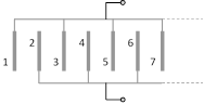 Equivalent capacitance \[C'=(n-1)\,C\] where \[C=\] capacitance of a capacitor \[=\frac{{{\varepsilon }_{0}}A}{d}\]
 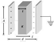 (vii) If a number of dielectric slabs are inserted between the plate as shown
 \[C'=\frac{{{\varepsilon }_{0}}A}{d-({{t}_{1}}+{{t}_{2}}+{{t}_{3}}+........)+\left( \frac{{{t}_{1}}}{{{K}_{1}}}+\frac{{{t}_{2}}}{{{K}_{2}}}+\frac{{{t}_{3}}}{{{K}_{3}}}+........ \right)}\]
(viii) When a metallic slab is inserted between the plates \[C'=\frac{{{\varepsilon }_{0}}A}{(d-t)}\]
\[C'=\frac{{{\varepsilon }_{0}}A}{d-({{t}_{1}}+{{t}_{2}}+{{t}_{3}}+........)+\left( \frac{{{t}_{1}}}{{{K}_{1}}}+\frac{{{t}_{2}}}{{{K}_{2}}}+\frac{{{t}_{3}}}{{{K}_{3}}}+........ \right)}\]
(viii) When a metallic slab is inserted between the plates \[C'=\frac{{{\varepsilon }_{0}}A}{(d-t)}\]
 If metallic slab fills the complete space between the plates (i.e. \[t=d\]) or both plates are joined through a metallic wire then capacitance becomes infinite.
(ix) Force between the plates of a parallel plate capacitor.
\[|F|\,=\frac{{{\sigma }^{2}}A}{2{{\varepsilon }_{0}}}=\frac{{{Q}^{2}}}{2{{\varepsilon }_{0}}A}=\frac{C{{V}^{2}}}{2d}\]
(x) Energy density between the plates of a parallel plate capacitor.
Energy density \[=\frac{Energy}{Volume}\]\[=\frac{1}{2}\,{{\varepsilon }_{0}}{{E}^{2}}.\]
Variation of different variable (Q, C, V, E and U) of parallel plate capacitor
If metallic slab fills the complete space between the plates (i.e. \[t=d\]) or both plates are joined through a metallic wire then capacitance becomes infinite.
(ix) Force between the plates of a parallel plate capacitor.
\[|F|\,=\frac{{{\sigma }^{2}}A}{2{{\varepsilon }_{0}}}=\frac{{{Q}^{2}}}{2{{\varepsilon }_{0}}A}=\frac{C{{V}^{2}}}{2d}\]
(x) Energy density between the plates of a parallel plate capacitor.
Energy density \[=\frac{Energy}{Volume}\]\[=\frac{1}{2}\,{{\varepsilon }_{0}}{{E}^{2}}.\]
Variation of different variable (Q, C, V, E and U) of parallel plate capacitor

 Dielectrics are insulating (non-conducting) materials which transmits electric effect without conducting.
Dielectrics are of two types
(1) Polar dielectrics : A polar molecule has permanent electric dipole moment \[(\vec{p})\] in the absence of electric field also. But a polar dielectric has net dipole moment zero in the absence of electric field because polar molecules are randomly oriented as shown in figure.
Dielectrics are insulating (non-conducting) materials which transmits electric effect without conducting.
Dielectrics are of two types
(1) Polar dielectrics : A polar molecule has permanent electric dipole moment \[(\vec{p})\] in the absence of electric field also. But a polar dielectric has net dipole moment zero in the absence of electric field because polar molecules are randomly oriented as shown in figure.
 In the presence of electric field polar molecules tends to line up in the direction of electric field, and the substance has finite dipole moment e.g. water, Alcohol, \[C{{O}_{2}}\], \[N{{H}_{3}}\], HCl etc. are made of polar atoms/molecules.
(2) Non polar dielectric : In non-polar molecules, Each molecule has zero dipole moment in its normal state.
When electric field is applied, molecules becomes induced electric dipole e.g. \[{{N}_{2}}\], \[{{O}_{2}}\], Benzene, Methane etc. are made of non-polar atoms/molecules
In general, any non-conducting, material can be called as a dielectric but broadly non conducting material having non polar molecules referred to as dielectric.
(3) Polarization of a dielectric slab : It is the process of inducing equal and opposite charges on the two faces of the dielectric on the application of electric field.
In the presence of electric field polar molecules tends to line up in the direction of electric field, and the substance has finite dipole moment e.g. water, Alcohol, \[C{{O}_{2}}\], \[N{{H}_{3}}\], HCl etc. are made of polar atoms/molecules.
(2) Non polar dielectric : In non-polar molecules, Each molecule has zero dipole moment in its normal state.
When electric field is applied, molecules becomes induced electric dipole e.g. \[{{N}_{2}}\], \[{{O}_{2}}\], Benzene, Methane etc. are made of non-polar atoms/molecules
In general, any non-conducting, material can be called as a dielectric but broadly non conducting material having non polar molecules referred to as dielectric.
(3) Polarization of a dielectric slab : It is the process of inducing equal and opposite charges on the two faces of the dielectric on the application of electric field.
 (i) Electric field between the plates in the presence of dielectric medium is \[E'=E-{{E}_{i}}\] where E = Main field, E' = Induced field.
(ii) Dielectric constant of dielectric medium is defined as :
\[\frac{E}{E'}=\frac{\text{Electric field between the plates with air}}{\text{Electric field between the plates with medium}}=K\]
(iii) K is also known as relative permittivity \[({{\varepsilon }_{r}})\] of the material or SIC (Specific Inductive Capacitance)
(4) Dielectric breakdown and dielectric strength : If a very high electric field is created in a dielectric,. The dielectric then behaves like a conductor. This phenomenon is known as dielectric breakdown.
The maximum value of electric field (or potential gradient) that a dielectric material can tolerate without it's electric breakdown is called it's dielectric strength.
S.I. unit of dielectric strength of a material is \[\frac{V}{m}\] but practical unit is \[\frac{kV}{mm}\].
(i) Electric field between the plates in the presence of dielectric medium is \[E'=E-{{E}_{i}}\] where E = Main field, E' = Induced field.
(ii) Dielectric constant of dielectric medium is defined as :
\[\frac{E}{E'}=\frac{\text{Electric field between the plates with air}}{\text{Electric field between the plates with medium}}=K\]
(iii) K is also known as relative permittivity \[({{\varepsilon }_{r}})\] of the material or SIC (Specific Inductive Capacitance)
(4) Dielectric breakdown and dielectric strength : If a very high electric field is created in a dielectric,. The dielectric then behaves like a conductor. This phenomenon is known as dielectric breakdown.
The maximum value of electric field (or potential gradient) that a dielectric material can tolerate without it's electric breakdown is called it's dielectric strength.
S.I. unit of dielectric strength of a material is \[\frac{V}{m}\] but practical unit is \[\frac{kV}{mm}\]. 


